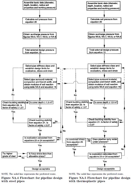
Steel pipe design differs from rigid pipe design in that the loads imposed by the soil on flexible steel pipe are different, and the steel pipe’s response to loading is different. Instead of resisting the loads through the strength of the pipe, instead the steel pipe deflects mobilizing the strength of the surrounding soils. For this reason the strength of the surrounding materials and backfill are critical to determining the structural capacity of the pipe-soil-surround system.
In the UK steel and plastic pipes are designed in the same way, using the flexible pipe design method taken from BS EN 1295-1.
Steel Pipe Design
The strength of the pipe-soil-surround system as a whole must be evaluated. This is done by estimating the stiffness of the three separate components and combining them into an overall modulus of soil reaction, often known as the Spangler modulus. This is a semi-empirical parameter and cannot be measured onsite, but has proved to be a useful method of evaluating the system stiffness in practice.
Then the suitability of the steel pipe itself depends on two design checks evaluating the allowable deflection as well as the structural capacity for the steel pipe to resist buckling. The allowable deflection is more a serviceability limit state as the steel pipe is intact though the hydraulic capacity is diminished. A general design procedure taken from BS EN 1295-1 is shown below.
Vertical Soil Pressures in Steel Pipe Design
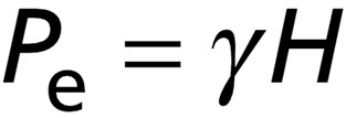
The first step in flexible steel pipe design is to determine the force acting on the pipe due to the dead weight of the backfill. This is calculated differently from rigid pipes because flexible steel pipes will deflect more than the columns of fill to either side. This effectively sheds load to the soil columns either side of the steel pipe reducing the load acting on the pipe itself. This means that the worst case loading acting on a flexible steel pipe occurs after the settlement of the soils and consequent load shedding has occurred. For this reason the backfill load acting on the pipe is simply the geostatic load from the soil above the pipe, as shown in the below equation where Pe is the backfill pressure, γ is the unit weight of the soil as described in the previous section and H is the backfill depth of soil above the pipe.
This vertical soil load is then added to the internal water load, the concentrated surcharge load and any further surcharges to find the total load acting on the steel pipe.
Effective Overall Modulus of Soil Reaction (E’)
This parameter is used to account for the stiffness of the pipe-soil system and is often referred to as the Spangler Modulus. Further information is available here.
Buckling Checks in Steel Pipe Design
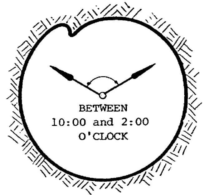
The first structural design check is to ensure that the steel pipe ring will not buckle due to the imposed loads. A diagram showing typical buckling failure is shown below. As flexible pipe materials such as thermoplastics often change their material properties over time, this design check needs to be done to cover both short term and long term loads and material properties. The long term properties include for creep. Note that steel pipes are not affected by creep so the design checks for long and short term loads will be the same.
Critical Buckling Pressure (Pcr)
First the critical buckling pressure can be calculated using the below equation. Note that for plastic pipe design this equation must be evaluated twice, once with the long term value for the modulus of elasticity to produce Pcrl and once with the short term value to produce Pcrs. Further details on these parameters are provided below.
Steel Pipe Modulus of Elasticity (E)
The modulus of elasticity value describes the stiffness of the pipe material. Many different types of materials are used for flexible pipes including many different metals and plastics, so this value can vary widely.
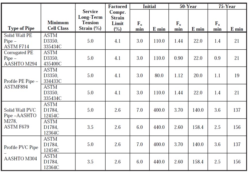
Typical values include 200GPa for steel (which does not deteriorate over time), and plastic pipes can be estimated from the below table taken from US standards (note this is in US units of Kip/in2, this can be converted to MPa by multiplying by a conversion factor of 6.895).
Mean Diameter of Pipe (D)
This is the average diameter of the pipe. The CivilWeb Buried Pipe Design spreadsheet determines this value by simply averaging the nominal and outside diameters as input by the designer.
Effective Overall Modulus of Soil Reaction (E’)
This is the overall stiffness modulus for the combined pipe-bedding-soil system.
Pipe Wall Second Moment of Area (I) (or Inertia)
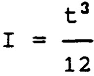
This property is simple to calculate if the pipe is a simple ring with a constant wall thickness. Note this is the inertia of the pipe wall, not the pipe itself. In this case the CivilWeb Buried Pipe Design spreadsheet uses the below equation to calculate the pipe wall inertia from the pipe wall thickness (t);
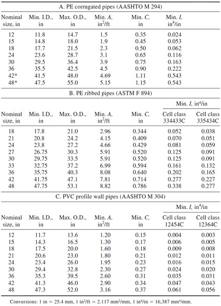
However, the pipe wall structures of flexible pipes varies widely from plain steel pipes to corrugations and ribs of many different types. Calculating the inertia of these sections is much more difficult and detailed geometrical information is required. For this reason the CivilWeb Buried Pipe Design spreadsheet allows the designer to override the default inertia calculated by the program. Where corrugated or ribbed pipes are proposed the inertia must be taken from the manufacturer. Where this information is unavailable, the below table taken from US standards gives an indication of typical values (note the US units).
Factor of Safety Against Buckling in Steel Pipe Design
The long term and short term critical buckling pressures calculated above can now be evaluated against the imposed loadings to calculate the overall factor of safety against buckling. This equation combines the long term loadings of backfill pressure divided by the long term critical buckling pressure with the short term loadings of concentrated surcharge and any vacuum pressure divided by the short term critical buckling pressure to create a combined factor of safety. The equation is shown below;
The required overall factor of safety against buckling is often taken as a high value of between 2.0 and 2.5 depending on the level of confidence the designer has in the accuracy of the inputs. However BS EN 1295-1 allows for a factor of safety of at least 1.5 at depths less than 1.5m, and a factor of safety of at least 2.0 for depths greater than 1.5m.
Buckling Check for Steel Pipes Without Soil Support
For steel pipes laid less than 1.5m deep, a further check is required that the pipe ring will not buckle in the case of an adjacent excavation temporarily removing the soil support from the side of the pipe. For this condition a new critical buckling pressure in air must be calculated using the below equation which is equivalent to Timoshenko’s critical buckling formula. Note this uses the short term modulus of elasticity.
Ovalisation (Pipe Ring Deflection)in Steel Pipe Design (Δ/D)
The other design check is to calculate the ovalisation or pipe ring deflection caused by the loading on the steel pipe. While all flexible pipes will deflect under load to some degree by definition, this deflection must be limited. While not strictly a structural failure, if the pipe deflects too much under the imposed loads this will affect the hydraulic performance of the pipe.
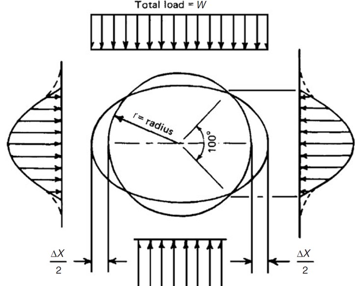
The method detailed in BS EN 1295-1 is a variation of the Spangler method used worldwide. The deflection is calculated basically as the load divided by the total stiffness of the pipe and soil system. The load system assumed in the Spangler method is illustrated in the below diagram.
The ovalisation (Δ/D) of the pipe is calculated using the below equation. The ovalisation must be calculated for both the initial condition using the short term value for modulus of elasticity and for the long term condition using the long term value for modulus of elasticity.
Deflection Coefficient (Kx)
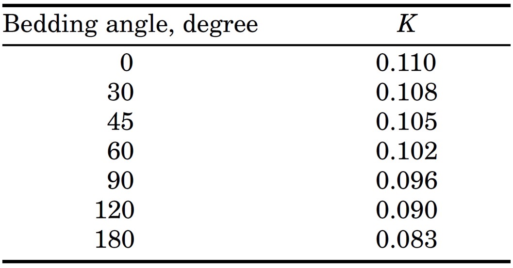
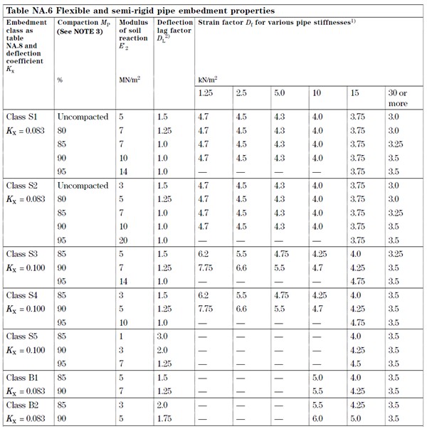
The deflection coefficient allows for the effects of the bedding type on the deflection of the pipe. This factor has been shown to vary between around 0.083 and 0.11. BS EN 1295-1 however recommends values of either 0.083 or 0.1 depending on the embedment class, as can be seen in the below table. The small reduction is to allow for any inconsistent haunch support.
The deflection coefficient can also be calculated using the below formula where α is the bedding angle. The deflection coefficient can also be taken from the below table.
Deflection Lag Factor (DL)
The deflection lag factor is included to allow for the time dependent nature of soil consolidation. The deflection lag factor depends on the embedment class and the level of compaction achieved, with highly compacted backfill given a value of 1.0 and less highly compacted backfill given a value of 1.5 or higher. Typical values are provided in BS EN 1295-1 as shown in the table below.
Backfill Pressure (Pe)
The backfill pressure is the pressure acting on the pipe from the weight of backfill over the pipe. This is calculated as above.
Concentrated Surcharge Pressure (Ps)
The concentrated surcharge pressure is the pressure imposed on the pipe from loading above ground such as from vehicles.
Modulus of Elasticity (E)
This is the elasticity of the pipe material. This can be determined as described above. Note that the short term value must be used for the initial ovalisation and the long term value for the long term ovalisation.
Second Moment of Area (I)
The second moment of area of the pipe wall or inertia can be determined as above.
Mean Pipe Diameter (D)
This is the average diameter of the pipe. The CivilWeb Buried Pipe Design spreadsheet determines this value by simply averaging the nominal and outside diameters as input by the designer.
Effective Overall Modulus of Soil Reaction (E’)
This is the overall stiffness modulus for the combined pipe-bedding-soil system.
Maximum Allowable Deflection in Steel Pipe Design
The CivilWeb Buried Pipe Design spreadsheet calculates the pipe ovalisation under initial and long term conditions. These results are then simply compared against the user defined maximum deflection in percent. This maximum allowable deflection is usually specified by the design standard used or by the pipe manufacturer and can be dependent on either hydraulic or structural requirements.
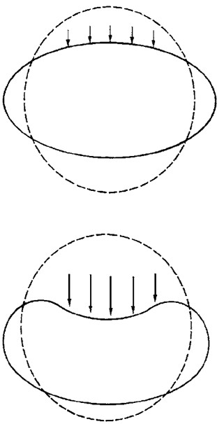
Structural design codes sometimes specify a maximum value of around 8% - 10% would be sufficient to prevent structural failure of the pipe. This is because a reversal in the curvature of the pipe as shown to the right does not occur until around 20% deflection in corrugated steel pipes and around 30% deflection in PVC pipes.
A value of 6% is often specified in the UK. This can however vary depending on manufacturer’s recommendations, hydraulic design considerations and the tolerance of any pipe liners or other components on deflection. The CivilWeb Buried Pipe Design spreadsheet allows the user to define the allowable deflection as a percentage of the mean pipe diameter.
Get your copy of the CivilWeb Buried Pipe Design spreadsheet including full steel pipe design now for only £20.
Or why not bundle the CivilWeb Buried Pipe Design spreadsheet with our Pipe Flow Calculator for only £5 extra?
Or save £50 by buying our full Drainage Design Suite including all our drainage design spreadsheets.
Download Free Trial Version
To try out a fully functional free trail version of this software, please Click Here or enter your email address below to sign up to our newsletter.
