The allowable Maximum Velocity in Pipe is often specified as part of the drainage design process, in addition to minimum velocities. High velocities within drainage pipe systems can cause a number of problems which are summarized below;
- Erosion of Pipe Materials – In the past it has been feared that high velocities would cause erosion of and damage to the pipe materials. While this may have been a justified concern in the past with brick sewers with weak mortar joints, modern drainage pipe materials are not generally affected by erosion in normal conditions. Where large volumes of hard grit sediments are expected in high velocity flows, it may be prudent to include some erosion resistant liners or materials, particularly where there are sharp changes of direction.
- Air Entrainment – Bulking of flow can occur as a result of air entrainment within the pipe at high velocities. This can reduce the capacity achieved in the pipe in surcharged conditions of between 20%-30%. The maximum velocity to avoid these effects can be checked using the below equation;
- Release of Hydrogen Sulphide – In some conditions hydrogen sulphide can be released at high velocities. This can lead to accelerated corrosion of the pipe.
- Super-Critical Flows – Super-Critical flows within drainage pipes should be avoided. Where super-critical flows are present there is a risk of an obstruction causing a hydraulic jump within the pipe. If the energy line is not contained within the pipe, there is a risk of a hydraulic jump causing surcharging of the pipe. In some cases energy dissipation methods can be used to create a hydraulic jump at a defined location where the effects can be controlled.
Super-critical flows at half full conditions can be checked when the velocity is larger than the below;
- Thrust Restraints may be required in some high velocity conditions.
- Inspection – The inspection of pipes containing high velocity flows is unsafe and additional safety equipment and infrastructure may be required.
- Cavitation – In some conditions cavitation of the pipe interiors can occur which can lead to significant damage. This is however unlikely to become an issue until velocities of around 20m/s are reached. Where this is deemed possible, further checks should be undertaken to reduce the potential of cavitation occurring.
- Erosion at Outfalls – The discharge from the pipe outfall cannot be allowed to take place at velocities which can cause erosion of the water body into which the pipe outfalls.
Where the gradient of the pipe and the velocity is expected to be high, the following measures can be used to reduce the velocity;
- A flatter gradient and possibly larger diameter pipe can be installed to take the same flow at a lower velocity
- Backdrop manholes or manholes with steps can be used as energy dissipaters to reduce velocities
- Vortex manholes or other energy dissipating devices can be used
In the past maximum velocities of around 3.0m/s – 3.66m/s were imposed to protect the pipes from erosion. This is not generally a concern with modern pipe materials which can withstand velocities of 6.0m/s - 7.0m/s unless there is an unusual amount of sediments being transported with the water. Indeed velocities of up to 9.0m/s can be specified in concrete pipes with a sacrificial liner.
While erosion or cavitation are unlikely to be a concern, higher velocities do require additional checks on hydraulic performance such as super-critical flows and greater energy losses at junctions. For this reason it is advised that any velocities above 3.0m/s are subjected to greater checks, with a maximum velocity of 6.0m/s for normal drainage conditions. Where velocities greater than this are expected, additional work should be done to check that none of the detrimental effects listed above are likely to become an issue. The CivilWeb Pipe Flow Calculator spreadsheet allows the user to specify a maximum velocity. The spreadsheet then returns suitable values within the specified range, speeding up drainage pipe design.
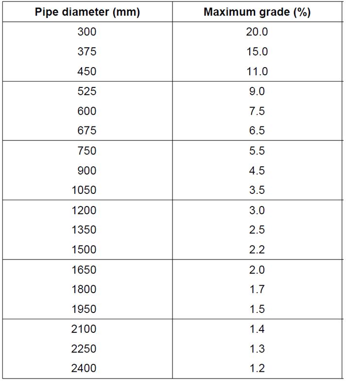
The table below has been produced to show the maximum gradient to limit the velocity to below 6.0m/s.
Get your copy of the CivilWeb Pipe Flow Calculator spreadsheet now for only £20.
Or why not bundle the CivilWeb Pipe Flow Calculator with our Rainfall Calculator Spreadsheet for only £5 extra?
Related Spreadsheets from CivilWeb;
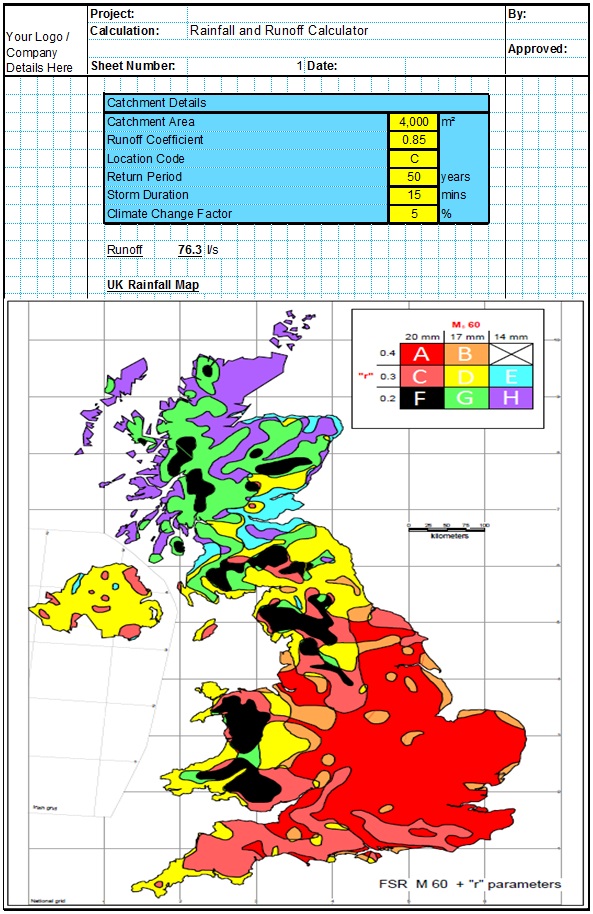
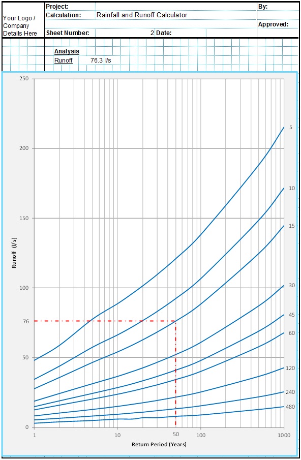
Runoff Calculator Spreadsheet
This spreadsheet calculates the design runoff flow for a site in accordance with the a number of different methods including the Wallingford Procedure.
Full Drainage Design Suite
Full drainage design suite (50% Discount) including 6 spreadsheet suites;
- Pipe Flow Calculator
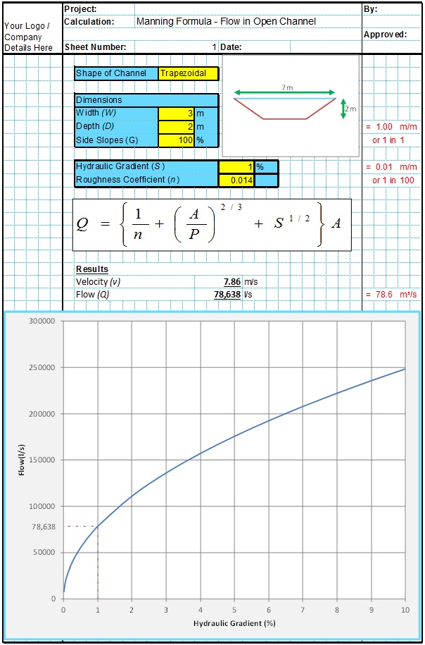
- Manning Open Channel Design
- Linear Drainage Design
- Runoff Calculator
- Attenuation Design
- Soakaway Design


