The below procedure is used by the CivilWeb High Mast Light Pole Design Spreadsheet to calculate the allowable bending moment capacity of typical steel high mast light poles. The spreadsheet uses this bending moment capacity to compare with the design bending moment induced by the wind loads and pressures acting on the high mast light pole. The procedure is taken from ILE technical Report 7 which is the standard method for designing and evaluating high mast light poles in the UK.
ILE Technical Report 7 states that steel high masts light poles can be designed using the plastic moment of resistance so long as the steels used comply with BS EN 10025. Where the ratio of the high mast light pole diameter and the steel thickness is less than 200, the following equation can be used to calculate the design plastic moment of resistance;
High Mast Light Pole Section Plastic Moment of Resistance (Mp) (Nm)
This is equivalent to the Plastic Modulus (Zp) of the high mast light pole section multiplied by the Characteristic Yield Strength (σy).
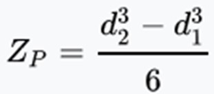
High Mast Light Pole Section Plastic Modulus (Zp) (mm3)
The plastic modulus of the high mast light pole section depends on the size and shape of the cross section at the point being considered and can be taken from the manufacturer. Alternatively the equation for a circular cross section can be calculated using the below equation where d1 is the overall diameter and d2 is the internal (hollow) diameter.
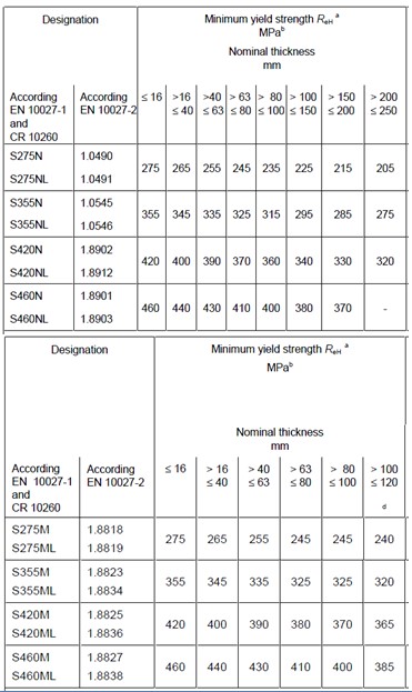
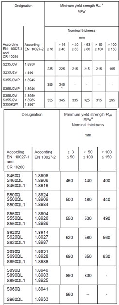
Characteristic Yield Strength (σy) (N/mm2)
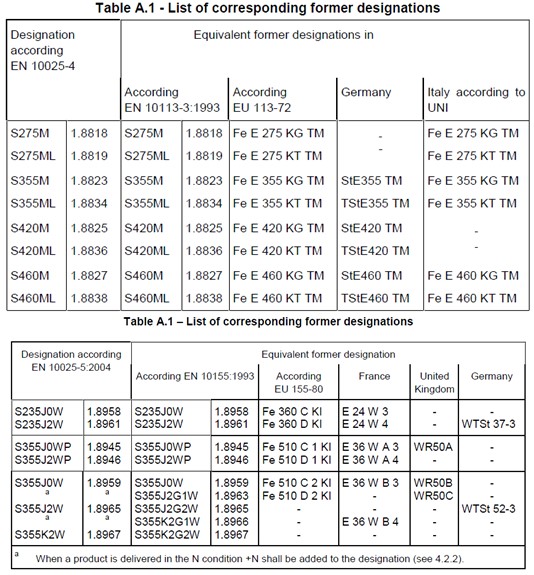
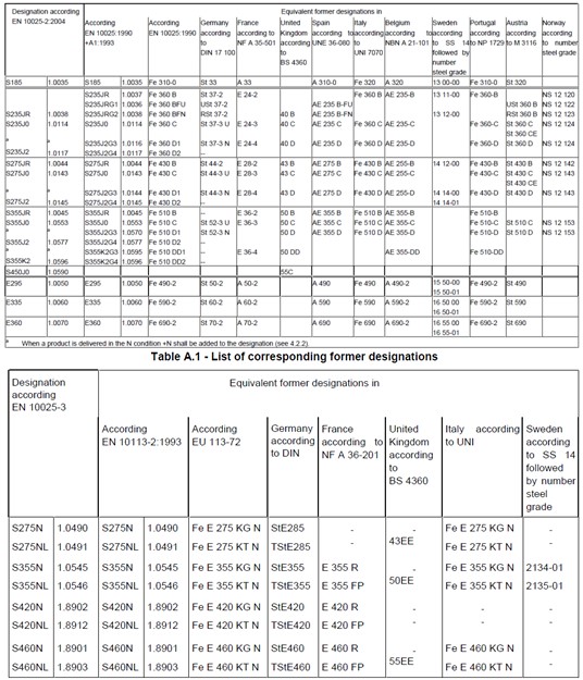
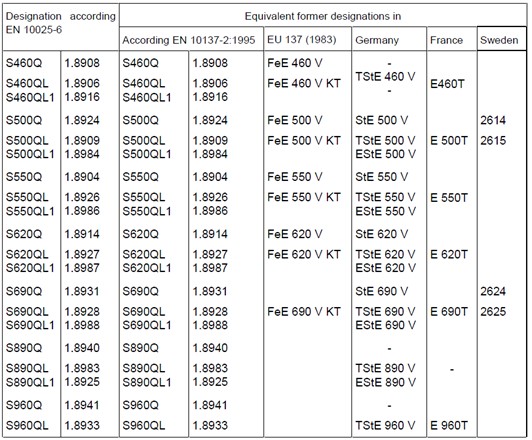
The characteristic yield strength of the high mast light pole describes the strength of the steel. This refers to the minimum yield strength or 0.2% proof stress of the steel. This can be provided by the manufacturer. Alternatively this can be estimated from the tables shown below taken from BS EN 10025. Historical designations are also given below for use evaluating older high mast light poles.
High Mast Light Pole Diameter at Base (D) (mm)
This is the diameter of the high mast light pole if circular, if not it is the distance across flat parts of the section. This is taken at the base of the mast where the maximum bending moment will be, typically at the base of the high mast light pole.
Steel Thickness (t) (mm)
This value describes the thickness of the steel and is measured in mm.
Number of Sides (N)
This is the total number of sides of the high mast light pole section. For circular sections or polygons with more than 20 sides, this can be taken as 20.
Young’s Modulus (E) (N/mm2)
The Young’s Modulus or Elastic Modulus of the high mast light pole section. This describes the elasticity of the steel. This value can vary slightly between different steel strengths and thicknesses but is often taken as 210,000 N/mm2. The mast manufacturer will be able to provide an accurate value for the steel used, though this will not have a large effect on the calculated allowable moment capacity of the high mast light pole.
Steel Safety Factor
This is a factor applied to account for any irregularities in manufacturing the steel itself and the section shape and dimensions. ILE Technical Report 7 advises that a value of 1.15 is used for steel high mast light poles.
Conclusion
This calculation is then compared by the CivilWeb High Mast Light Pole Design Spreadsheet to the calculated maximum bending moment to check that the proposed pole section is adequate.
Get your copy of the CivilWeb High Mast Light Pole Design Spreadsheet including allowable bending moment calculations now for only £20.
Or why not bundle the CivilWeb High Mast Light Pole Design Spreadsheet with our Street Light Foundation Design Spreadsheet for only £5 extra?
Download Free Trial Version
To try out a fully functional free trail version of this software, please Click Here or enter your email address below to sign up to our newsletter.

