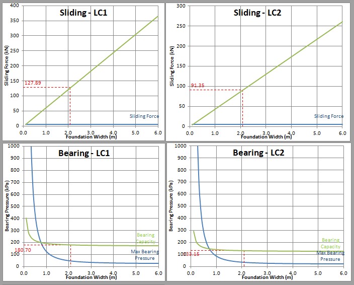
Sign post pad foundation design is undertaken in basically the same way as any other small spread foundations according to BS EN 1990, 1991 and 1997. The sign post pad foundation must be checked for stability against overturning, sliding, bearing pressure and settlement. The CivilWeb Sign Post Foundation Design Calculator calculates the required pad foundation dimensions in accordance with BS EN 1997 automatically making concrete sign post pad foundation design easier than ever.
Sign Post Pad Foundation Design - Soil Parameters
Firstly the designer must choose some simple soil parameters to enable the sign post pad foundation design to be checked. Site investigation information is often undertaken as part of any larger site or road projects undertaken at the same time as the sign installation, but it is not common for site investigation to be done just for sign posts installed on an existing site.
Where site investigation information is not available, typical values are often used. Usually it is assumed that the soil is reasonably poor, so a bearing capacity of around 100kN/m2 is often used.
If site investigation information is available the soils can be more accurately modeled based on their Undrained Shear Strength (cu) and the Unit Weight of the Soil (gsoil). If this specific information is unavailable it can often be estimated from other basic soil observations and measurements.
Sign Post Pad Foundation Dimensions
Next the designer must choose the dimensions of the sign post pad foundation. Usually it is economical to minimize the length parameter which will need to be large enough to accommodate the width of the sign, particularly where more than one sign post is to be used. Then the depth can be set at an appropriate value, usually around 0.5m – 1.0m for large highway sign posts. Finally the designer can tweak the width value until the design is adequate. This is usually the most economical sign post pad foundation design approach because the width value is the most effective dimension to increase as this value increases the amount of concrete in the direction of the wind load on the sign. If the width becomes too large, then the depth can be adjusted to suit the maximum practical width.
The CivilWeb Sign Post Foundation Design Calculator includes unique design graphs showing the user the minimum width to achieve all the relevant design conditions, making it easy for the designer to optimize the base dimensions.
Loss of Equilibrium (EQU Limit State)
The proposed sign post pad foundation must be checked against loss of equilibrium, or the EQU Limit State. In sign post pad foundation design this is unlikely to be the critical factor, however the CivilWeb Sign Post Foundation Design Calculator checks this value in accordance with BS EN 1997. To check for Loss of Equilibrium the destabilizing moment is checked against the restoring moment.
Destabilising Moment (Edst;k)
The destabilizing moment caused by wind pressure on the sign can be calculated using the following formula where Frep is the Wind Force, z is the height of the sign centroid above the ground, hb is the depth of any soil above the sign post pad foundation and T is the foundation depth;
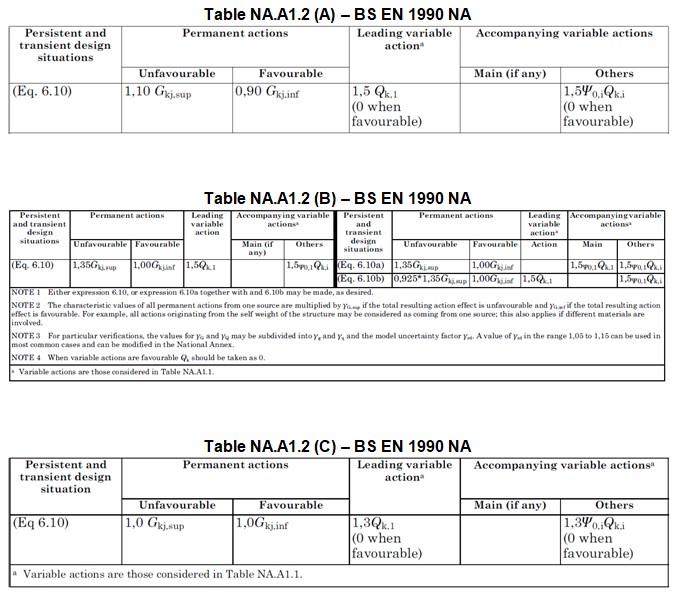
A partial factor (γG;dst) is then applied to calculate the design destabilizing moment (Edst;d). A partial factor of 1.50 is typically used for a leading variable action such as wind as taken from Table NA.A1.2 (A) – BS EN 1990 NA as shown at the bottom of this page.
Restoring Moment (Estb,k)
The restoring moment can be calculated using the below equation where Wk is the total weight of the sign post pad foundation (length x width x depth x density (usually around 24.0kN/m3) and L is the foundation width.
This is then converted to the design value (Estb,d) by applying a partial factor, usually taken as 0.9 for favorable permanent actions such as dead weight of a concrete foundation base.
Loss of Equilibrium (EQU Limit State) - Conclusion
The pad foundation is then considered safe if the restoring moment is greater than or equal to the destabilizing moment. Note that shearing resistance can be included but is unlikely to be significant in typical sign post pad foundation design.
Failure or Excessive Deformation of the Ground (GEO Limit State) - Overturning
For all GEO Limit States the GEO Design Approach 1 is considered suitable for sign post pad foundation design in the UK. This includes load combinations 1 and 2 as shown below;
Combination 1 – A1 + M1 + R1
Combination 2 – A2 + M2 + R1
It is also considered appropriate to use the partial factors applicable to buildings, rather than the more onerous factors used for bridges.
The proposed sign post pad foundation must be checked against overturning due to the failure of the ground. This can occur when the maximum bearing pressure at the edge of the foundation exceeds the soils bearing capacity causing a rotation of the foundation. This must be done for both load combinations 1 and 2.
In some cases this check can be discounted such as for clay soils or if the risk of some tilting of the sign in extreme wind conditions is considered an acceptable risk.
Destabilising Moment (Ek) – Load Combination 1
The destabilizing moment caused by wind pressure on the sign can be calculated using the below equation where Frep is the Wind Force, z is the height of the sign centroid above the ground, hb is the depth of any soil above the foundation and T is the foundation depth;
A partial factor (γf) is then applied to calculate the design destabilizing moment (Ed). A partial factor of 1.50 is typically used for a leading variable action such as wind as taken from Table NA.A1.2 (B) – BS EN 1990 NA as shown at the bottom of this page.
Restoring Moment (Rk) – Load Combination 1
The restoring moment can be calculated using the below equation where Wk is the total weight of the sign post pad foundation (length x width x depth x density (usually around 24.0kN/m3), L is the foundation width, YK is equal to Wk and x is the eccentricity (from the foundation edge).
Failure or Excessive Deformation of the Ground (GEO Limit State) - Overturning Conclusion
The required maximum eccentricity (x) can then be determined by rearranging this equation (the partial factor for favorable permanent actions taken from the above table is 1.0). If this eccentricity is negative then the foundation is too small.
Load Combination 2
This process is then repeated for load combination 2, using a different partial factor of 1.30 as taken from Table NA.A1.2 (C) – BS EN 1990 NA as shown as shown at the bottom of this page.
Again the required eccentricity should be positive (ie within the extents of the foundation).
Failure or Excessive Deformation of the Ground (GEO Limit State) - Sliding
The sign post pad foundation must be checked so that the forces acting on the sign do not cause the foundation to slide backwards through the soil. Again the sliding check must be done against load combinations 1 and 2.
Sliding Force (Hd) – Load Combination 1
The sliding force is simply equivalent to the Total Wind Force multiplied by the partial factor, which for unfavorable variable action is 1.5 as taken from Table NA.A1.2 (B) – BS EN 1990 NA as shown at the bottom of this page.
Resistance Force (Rd) – Load Combination 1
The resistance of the soils to sliding is dependent on the area of the foundation and the shear strength of the soils. Therefore the resistance to sliding can be calculated using the following equation where A is the foundation base area and Cu;d is the undrained shear strength of the soil multiplied by the partial factor, which can be taken as 1.0 in this case, as shown in the table below.
Failure or Excessive Deformation of the Ground (GEO Limit State) - Sliding - Conclusion
The sign post pad foundation is considered safe if the resistance force is larger than or equal to the sliding force.
Load Combination 2
This process is then repeated for load combination 2, using a different soil partial factor taken from the above table (M2 is 1.4) and a different load partial factor of 1.30 taken from Table NA.A1.2 (A) – BS EN 1990 NA as shown at the bottom of this page.
Failure or Excessive Deformation of the Ground (GEO Limit State) – Bearing
The foundation must also be checked for bearing pressure failure of the ground. Again the bearing pressure check must be done against load combinations 1 and 2.
Bearing Pressure (Vd) – Load Combination 1
First the eccentricity of the reaction (from the base centroid) must be calculated using the below equation where L is the foundation width and x is the eccentricity calculated for the overturning moment (Load Combination 1).
If this value is less than L/6 then the reaction is within the central third of the foundation. This is considered best practice as this will remove the risk of negative bearing pressures trying to raise one side of the foundation, but is not essential.
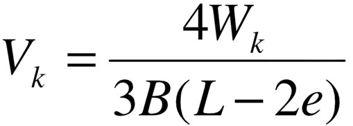
The maximum bearing pressure can be calculated using the below equation where Wk is the foundation weight (Length x Width x Depth x Density (usually around 24.0kN/m3), γf is the partial factor for ULS which is 1.35 taken from the below table (PAF Class 1), e is the eccentricity as calculated above, L is the foundation width, and W is the foundation length.
Bearing Capacity (Rd;v) – Load Combination 1
The bearing capacity of the soil can be calculated in a number of different ways from site bearing tests or soil properties. Where geotechnical information is not available a reasonably conservative value of 100kPa is often used.
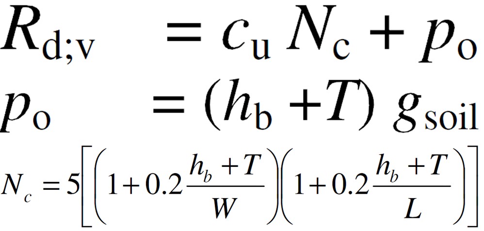
The CivilWeb Sign Post Foundation Design Calculator includes one method of estimating soil bearing pressure capacity from the soil undrained shear strength and unit weight. These equations are shown below where cu is the undrained shear strength of the soil, hb is the height of any soil on top of the foundation, T is the base depth, gsoil is the unit weight of the soil, W is the foundation length and L is the foundation width.
Failure or Excessive Deformation of the Ground (GEO Limit State) – Bearing Conclusion
The sign post pad foundation is considered safe if the soil bearing capacity is larger than or equal to the maximum bearing pressure.
Load Combination 2
This process is then repeated for load combination 2, using the overturning eccentricity calculated for combination 2, using a different soil partial factor taken from the below table (M2 is 1.4) and a different load partial factor of 1.00.
Sign Post Pad Foundation Design - Settlement Check
Finally the proposed foundation has to be checked for potential settlement issues. As the foundations for typical road signs are relatively simple and not particularly sensitive to settlement, it is deemed reasonable that detailed settlement calculations are not undertaken. Instead the CivilWeb Sign Post Foundation Design Calculator assumes that the settlements will be suitably limited if the bearing capacity of the soils is at least 3 times the applied bearing pressures. If this case is not met then the spreadsheet recommends more detailed site investigation and settlement calculations are undertaken.
Destabilising Moment (Ek)
The destabilizing moment is calculated using the below equation where Frep is the Wind Force, z is the height of the sign centroid above the ground, hb is the depth of any soil above the foundation and T is the foundation depth;
Restoring Moment (Rk) and Eccentricity from Base Centre (e)
The restoring moment can be calculated using the below equation where Wk is the total weight of the concrete base (length x width x depth x density (usually around 24.0kN/m3), L is the base width, Y is equal to Wk and x is the eccentricity (from the foundation edge).
The required maximum eccentricity (x) can then be determined by rearranging this equation. This eccentricity from the base edge is then converted to eccentricity from the base centre (e) using the following equation;
Maximum Bearing Pressure (Vk)
The maximum bearing pressure can now be calculated using the following equation if the reaction is within the central third of the foundation;
If the reaction is not within the central third of the foundation, the following equation must be used;
Allowable Bearing Capacity (Rall;v)
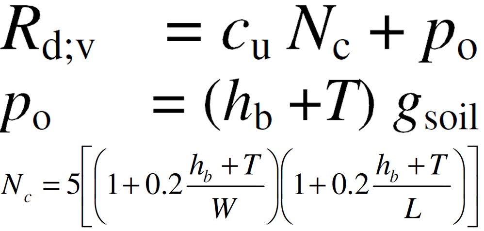
The maximum bearing pressure is now checked against the allowable bearing capacity of the soil. To calculate this first the ultimate bearing capacity (Rk;v) must be calculated using the below equation where cu is the undrained shear strength of the soil, hb is the height of any soil on top of the foundation, T is the base depth, gsoil is the unit weight of the soil, W is the foundation length and L is the foundation width.
Conclusion
The allowable bearing capacity is calculated as a third of the ultimate bearing capacity. If the maximum bearing pressure exceeds the allowable bearing pressure, then more detailed calculations are recommended, particularly where some moderate settlement of the foundation may be an issue.
CivilWeb Sign Post Foundation Design Calculator
Sign post pad foundation design is not often completed in detail because of the relative complexity of the design checks required and the typically low risk and cost of sign post pad foundations. It is however usually overly conservative to use standard pad foundation designs for a number of different sign posts. This is particularly the case for large signs where an optimised pad foundation design will deliver significant savings and increased understanding of the risks.
The CivilWeb Sign Post Foundation Design Calculator allows the designer to complete sign post pad foundation design in accordance with BS EN 1990, 1991 and 1997 in a matter of minutes. The designer simply inputs the sign parameters and the CivilWeb Sign Post Foundation Design Calculator calculates the required foundation dimensions and even suggests multiple suitable foundation sizes which the designer can simply choose the most appropriate. The CivilWeb Sign Post Foundation Design Calculator also competes the sign post design and can be used for embedded sign post foundation design also.
Get your copy of the CivilWeb Sign Post Foundation Design Calculator including detailed sign post pad foundation design now for only £20.
Or why not bundle the CivilWeb Sign Post Foundation Design Calculator with our Street Light Foundation Design Spreadsheet for only £5 extra?
Download Free Trial Version
To try out a fully functional free trail version of this software, please Click Here or enter your email address below to sign up to our newsletter.
Error: Contact form not found.


