Portal Frame Analysis
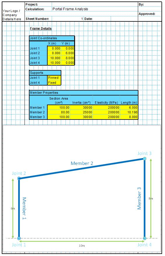
This spreadsheet undertakes the analysis of a user specified portal frame consisting of two vertical columns supporting a beam. The spreadsheet then returns the analysis results in the form of maximum and minimum values for each span and support, and generates charts to illustrate the analysis of the whole portal frame structure.
The Spreadsheet includes the following functions;
- Can model portal frame structures with two vertical supports of any length, and a beam of any length spanning between the two supports. The geometry of the structure is entered by the user entering co-ordinates for all 4 joint locations. The program then sketches the structure to illustrate what is being analysed.
- The column supports can be either pinned or fixed. The beam supports are assumed to be pinned.
- Can model portal frame structures of any material by modifying the Modulus of Elasticity. Different materials can be applied to each of the three members for analysis.
- Can model sections of any shape by modifying the cross sectional area and the Inertia. Each member can be different section and/or Inertia.
- Can model portal frame structures subject to any combination of more than 60 loading conditions, including;
- Dead and Imposed loadings applied directly to the joints
- Up to five different Distributed Loads for each member
- Up to five different Point Loads for each span member
- Up to five different Moments for each span member
- Output –
- The spreadsheet analyses the structure in three loading conditions (all members fully loaded, then imposed loads removed for alternate members).
- Returns values for maximum support reactions
- Returns values for maximum joint displacements
- Returns values for maximum member end forces
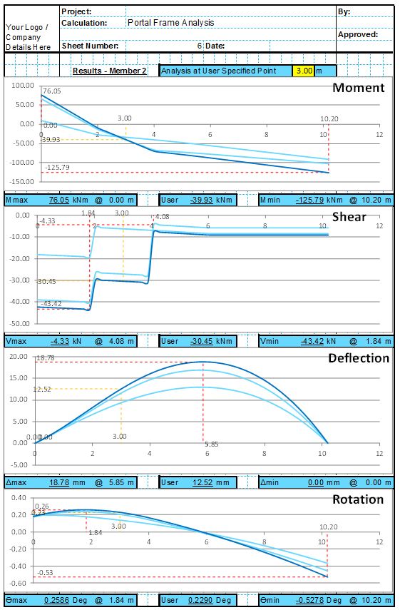
- Returns values for maximum and minimum bending moments and gives their precise location for each member. Also returns bending moment values at a user specified point and draws a chart showing the bending moments at all points on the member.
- Returns values for maximum and minimum shear and gives their precise location for each member. Also returns shear values at a user specified point and draws a chart showing the shear at all points on the member.
- Returns values for maximum and minimum deflection and gives their precise location for each member. Also returns deflection values at a user specified point and draws a chart showing the deflection at all points on the member.
- Returns values for maximum and minimum rotation and gives their precise location for each member. Also returns rotation values at a user specified point and draws a chart showing the rotation at all points on the member.
Get the full license version now for only £10.
All purchases are covered by our full money back guarantee.
Download Free Trial Version
To try out a fully functional free trail version of this software, please Click Here or enter your email address below to sign up to our newsletter.
Single Span Beam Analysis
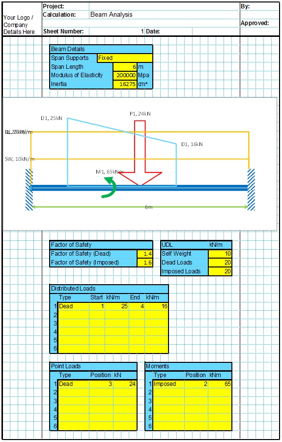
This spreadsheet undertakes the analysis of a user defined single span beam subject to a variety of user defined loading conditions.
Continuous Span Beam Analysis
This spreadsheet undertakes an analysis of a user defined continuous spanning beam subject to a variety of user defined loading conditions. It returns values for moment, shear, deflection and rotation of each span of the beam.
Two Way Spanning Slab Analysis
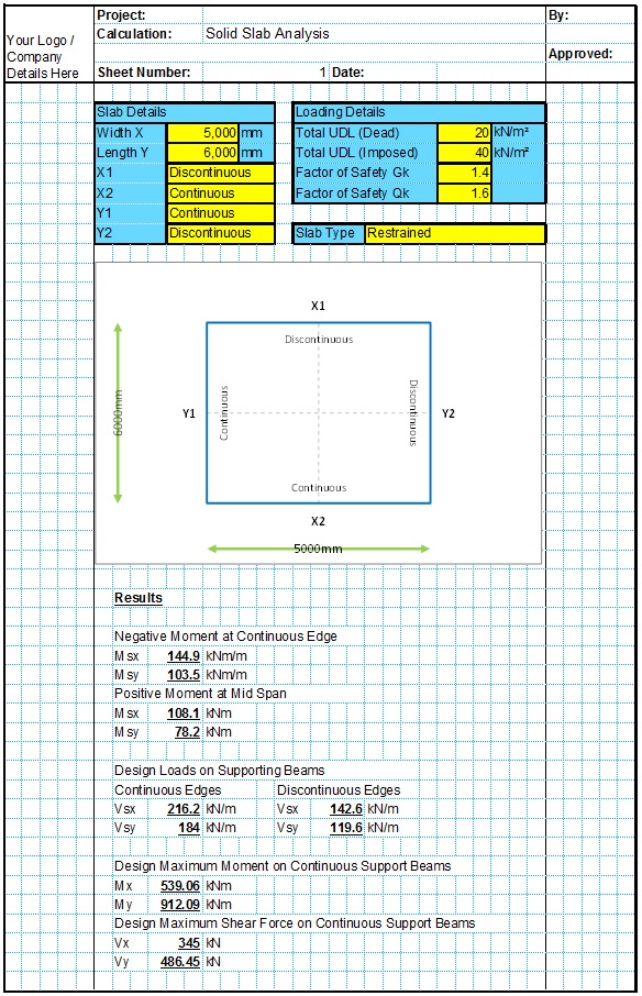
This Spreadsheet under takes the calculations outlined in BS8110 for the analysis of simple two way spanning slabs subject to UDLs.
Gable Frame Analysis
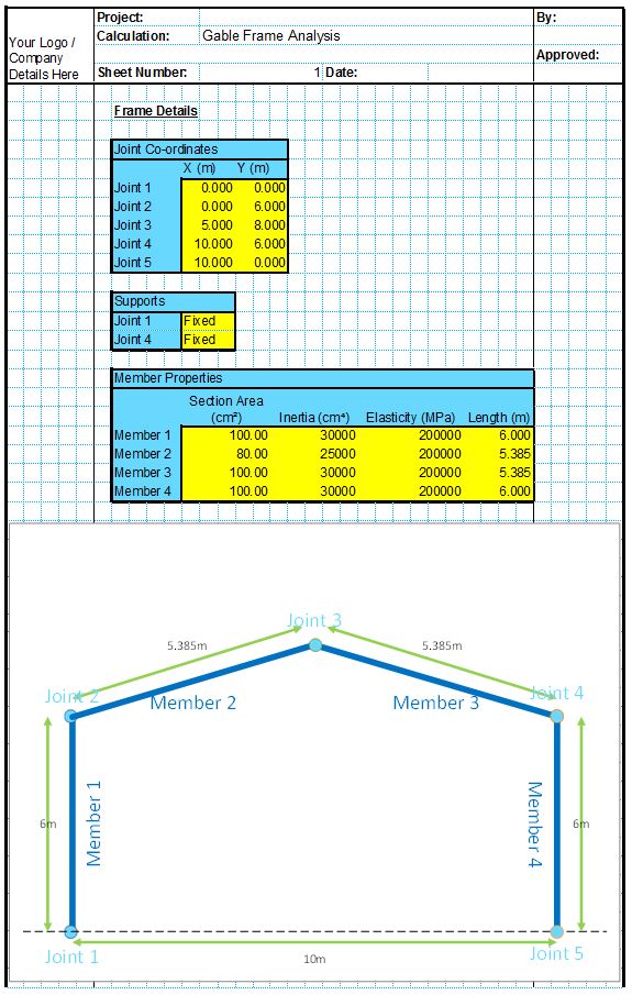
This spreadsheet analyses a simple user defined gable frame structure and returns values for bending moment, shear forces, deflection and rotation of each member.
