The pipe bedding factor is very important as this adds a great deal of strength to the pipe when it is in service. This factor can be anywhere between 10% and 120% or more of the total structural strength of the pipe/bedding system.
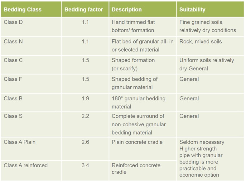
There are 7 main pipe bedding types used in the UK with concrete pipes. Five of these bedding types are included in all commonly used standards and specifications (N, F, B, S & A). Two further sub-classes are also sometimes specified in the UK (D & C). The below table gives the pipe bedding factors for each class and a short description. A detailed discussion of each pipe bedding class is included below.
Pipe Bedding Class D – Pipe Bedding Factor 1.1
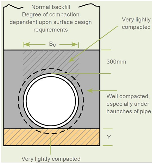
Pipe Bedding Class D consists of pipes installed directly onto a hand trimmed trench bottom, with care taken to fill any hollows. Socket holes should be installed where required providing at least 50mm of clearance under the pipe sockets. This bedding class is generally suitable in fine grained soils and dry conditions. This bedding class is illustrated in the diagram below.
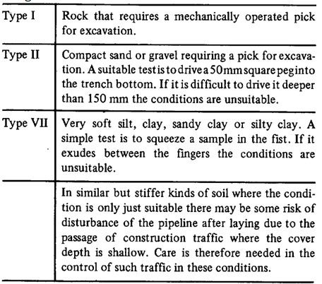
This bedding class requires that the soils making up the trench bottom are suitable for hand trimming and are not too soft. Soils with large rocks are unsuitable as these will leave either hard spots if left in or voids if removed. The pipes should make reasonably good contact with the ground. Some guidance on unsuitable soils is included in the table on the below taken from the Building Regulations;
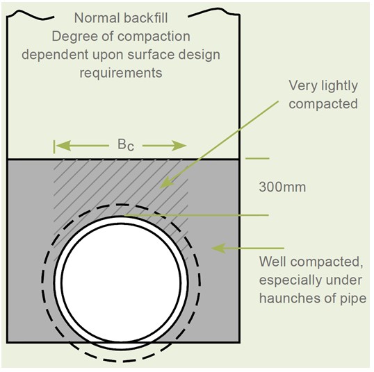
Pipe Bedding Class N – Pipe Bedding Factor 1.1
Pipe Bedding Class N includes a layer of selected fill or poor quality granular material. Socket holes should be installed where required providing at least 50mm of clearance under the pipe sockets. This bedding class is illustrated in the diagram below.
Bedding class N includes a bedding layer of poor quality material which is compacted before the pipe is laid on top. This layer does not provide a good quality support for the pipe as the pipe is unlikely to settle significantly into the bedding. For this reason the supporting strength and bedding factor is small.
Pipe Bedding Class C – Pipe Bedding Factor 1.5
Pipe Bedding Class C includes the bottom of the trench to be hand shaped in order to achieve around 45° support for the pipe. This bedding class is sometimes suitable in uniform soils and dry conditions. Socket holes should be installed where required providing at least 50mm of clearance under the pipe sockets. This bedding class is illustrated in the diagram below.
Generally scarifying the soils at the bottom of the trench is usually suitable to achieve this bedding type.
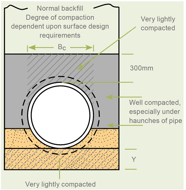
Pipe Bedding Class F – Pipe Bedding Factor 1.5
Pipe Bedding Class F consists of a flat granular layer of bedding onto which the pipe is installed. Holes should be included for sockets to ensure consistent pipe support is achieved. The pipes need to be able to settle slightly into the bedding. Socket holes should be installed where required providing at least 50mm of clearance under the pipe sockets. This bedding class is illustrated in the diagram below.
This bedding class is commonly specified and presents a useful compromise between laying the pipe on the trench bottom and more expensive bedding classes using much more granular material. Using less granular material also allows the pipe to be laid faster.
The pipe bedding factor of 1.5 depends on the granular material being laid flat and the weight of the pipe causing it to settle slightly into the bedding material after placement. This allows the bedding to provide support to the pipe of around 45° of the pipe circumference. This equates to a settlement of around 5% of the pipe nominal diameter. In normal placement conditions this settlement is achieved though this should be checked onsite where the higher supporting strength is required in the design.
Using a layer of granular material at the bottom of the trench avoids the difficulties with installing pipes on the bottom of the trench and also provides a greater supporting strength. In many cases it can be economical and faster to specify a higher strength pipe to compensate for the lower supporting strength of this bedding class compared to Class B or S beddings.
The tendency for ground water to flow along the line of the granular fill should be discouraged with the use of clay waterstops within the bedding or ensuring that manholes installed on the pipe line act as effective waterstops. If groundwater is allowed to flow through the bedding this can lead to problems with any fine materials being washed out or from erosion of the bedding material.
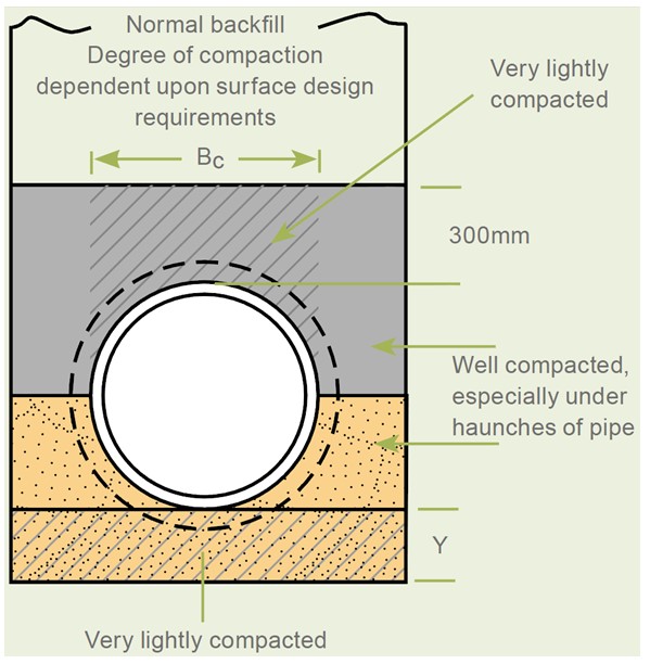
Pipe Bedding Class B – Pipe Bedding Factor 1.9
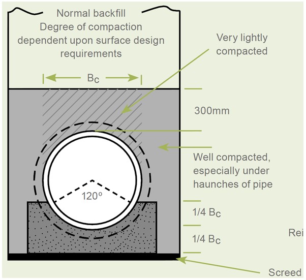
Pipe Bedding Class B includes a granular bedding encompassing 180° of the bottom of the pipe. The bedding material should be laid and compacted with holes included providing at least 50mm of clearance for any sockets. Sidefills should be densely compacted particularly beneath the haunches of the pipe with care taken not to displace the pipe during compaction. This bedding class is illustrated in the diagram below.
This type of bedding is very commonly specified. It provides a high supporting strength and avoids the difficulties associated with the laying of rigid pipes directly onto the trench bottom.
This bedding type does however allow some settlement of the pipe to occur. Where this is unacceptable a higher bedding class S or A should be specified. Also any excavations occurring close to the pipe in the future are more likely to disturb the pipe. The trench will also need to be wide enough to enable the bedding to be compacted after the pipe is installed. A trench conforming to the minimum trench widths recommended in BS EN 1610 will generally be suitable.
As above waterstops should be used to prevent the flow of groundwater through the granular bedding material.
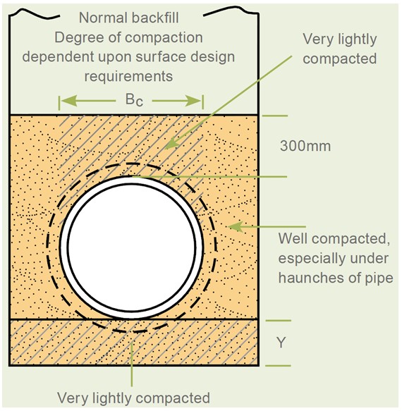
Pipe Bedding Class S – Pipe Bedding Factor 2.2
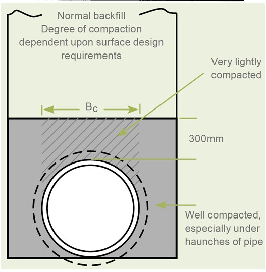
Pipe Bedding Class S includes a complete surround of the pipe with granular bedding material. Installed in a similar manner to Bedding Class B except the granular bedding is taken up to 300mm over the crown of the pipe. Care should be taken to leave a lightly compacted zone on top of the pipe. Socket holes should be installed where required providing at least 50mm of clearance under the pipe sockets. This bedding class is illustrated in the diagram below.
This bedding type is used when a high supporting strength is required or where it is desirable to avoid importing selected backfill over the top of the pipe.
The higher pipe bedding factor achieved by class S bedding is dependent on the compaction of the side fill. For this reason the supervision and control of the construction and installation process is required for this bedding class. In some cases achieving sufficient compaction is difficult for example where a narrow vee shaped trench is employed or where the pipe in question is installed at the higher level of a stepped trench. The trench must be sufficiently wide to enable the fill at the sides of the pipe to be adequately compacted. A trench conforming to the minimum trench widths recommended in BS EN 1610 will generally be suitable. In some cases such as those described above it is advised that a lower bedding factor similar to Class B is used for design purposes. Similar to Class F and B, effective waterstops should be included to prevent the flow of groundwater through the bedding.
Pipe Bedding Class A (Unreinforced) – Pipe Bedding Factor 2.6
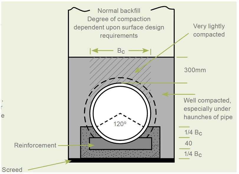
Pipe Bedding Class A (Unreinforced) includes an unreinforced concrete cradle encompassing 120° of the bottom of the pipe. This bedding class is illustrated in the diagram below.
This type of bedding is suitable where a very significant increase in strength is required, for example where heavy loads are expected on a small diameter pipe. It can also be useful where site conditions prevent granular bedding material from being used or where settlement of the pipe into the underlying soils must be minimized. A concrete cradle will however increase the loads acting on the pipe as the pipe external width used in the design should be increased to the width of the concrete cradle.
The bottom of the trench should be levelled with blinding concrete. Then the pipe should be supported on suitable concrete blocks or spacers behind each socket. Construction joints should be included through the concrete cradle at pipe joint locations to allow adequate flexibility.
The concrete cradle should be monolithic and should be poured from one side of the pipe only to avoid voids underneath the pipe. The concrete used should achieve a minimum 28 day compressive cube strength of 20N/mm2. As with any other type of concrete this must be allowed sufficient time to cure before loading. Generally this prevents the main backfill of the pipe until at least 24 hours after the placement of the concrete or until the concrete has achieved around 14N/mm2 compressive cube strength. Traffic loads should not generally be imposed until around 72 hours after placement. This time can be reduced by using fast setting concrete, a stronger concrete or steel plates over the trench to prevent premature loading.
Pipe Bedding Class A (Reinforced) – Pipe Bedding Factor 3.4
Pipe Bedding Class A (Reinforced) includes a reinforced concrete cradle encompassing 120° of the bottom of the pipe. This bedding class is illustrated in the diagram below.
This type of bedding is only required where a very high supporting strength is required. The considerations in using this type of bedding are similar to the above for unreinforced beddings. There should be at least 0.4% reinforcement steel in order to justify an increased bedding factor of 3.4.
Protective Concrete Arch (Unreinforced) – Pipe Bedding Factor 2.6
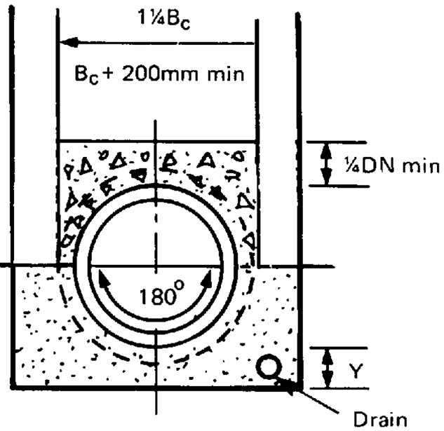
Similar to Bedding Class A, protective concrete arches can be installed on top of the pipe instead of concrete cradles being installed below. This bedding class is illustrated in the diagram below.
Protective concrete arches are only usually specified when a late increase in bedding factor is required after the pipe has been installed. This can be due to unforeseen ground conditions or changes in the expected loadings.
Protective arches are much easier to place generally compared to concrete cradles but they increase the loadings acting on the pipe. They do this by both decreasing the cover depth of material and usually be increasing the require trench width by around 25%.
The concrete should be installed to the same quality as described in Bedding Class A.
Protective Concrete Arch (Reinforced) – Pipe Bedding Factor 3.4 – 4.8
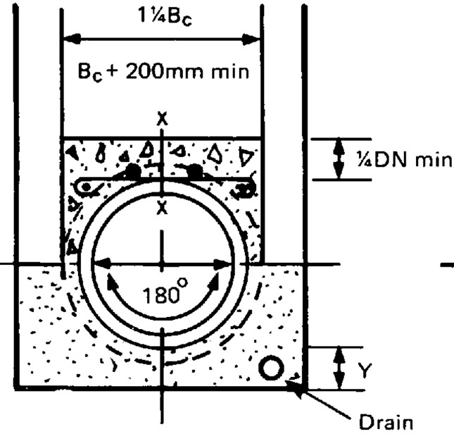
Protective concrete arches can also be installed with steel reinforcement. This bedding class is illustrated in the diagram below.
The concrete should be installed to the same standards as above and the steel reinforcement should be installed as close as possible to the top of the pipe allowing for adequate cover. The percentage of reinforcing steel can also be increased from around 0.4% to around 1.0% to increase the bedding factor from 3.4 to 4.8.
Full Concrete Surround – Pipe Bedding Factor 4.8 – 4.8
A full concrete surround is similar to the above but with a cradle below and an arch over the top of the pipe. This bedding class is illustrated in the diagram below.
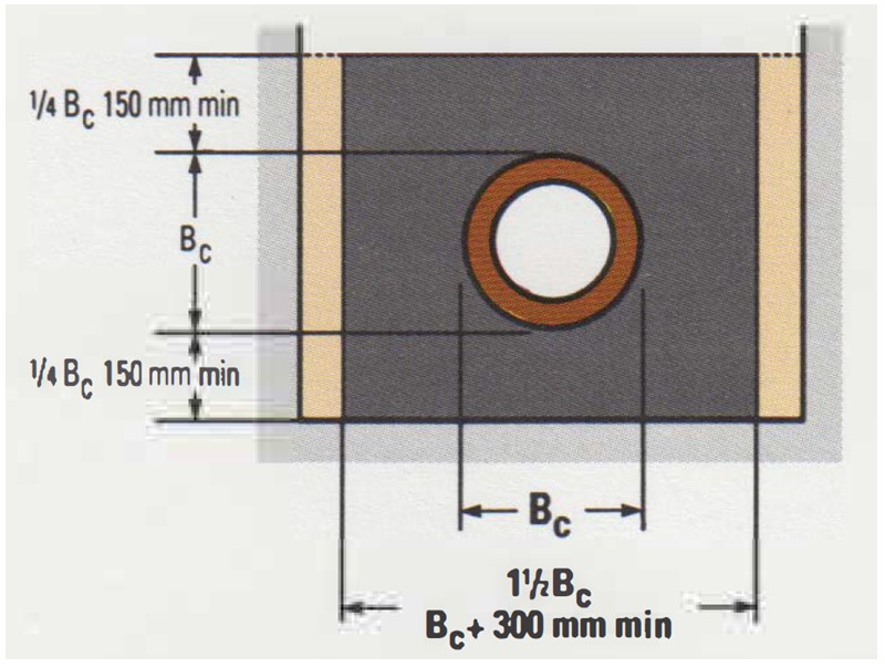
Increased bedding factors of 4.5 for unreinforced and 4.8 for reinforced concrete surrounds can be used. The higher value of 4.8 for reinforced concrete surrounds assumes 1.0% of steel reinforcement both above and below the pipe with vertical steel joining the two main steel sections. The surround should extend at least 150mm beyond the outside width of the pipe in order to utilize these bedding factors.
Get your copy of the CivilWeb Buried Pipe Design spreadsheet including full rigid, semi-rigid and flexible pipe design now for only £20.
Or why not bundle the CivilWeb Buried Pipe Design spreadsheet with our Pipe Flow Calculator for only £5 extra?
Or save £50 by buying our full Drainage Design Suite including all our drainage design spreadsheets.
Download Free Trial Version
To try out a fully functional free trail version of this software, please Click Here or enter your email address below to sign up to our newsletter.
