Cathodic protection systems are often installed to prevent or halt Accelerated Low Water Corrosion (ALWC). The CivilWeb Cathodic Protection Design Spreadsheet can be used to design cathodic protection systems which are effective in protecting against Accelerated Low Water Corrosion.
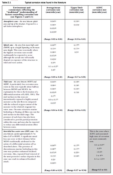
ALWC is an aggressive concentrated type of corrosion which occurs around the low water mark on marine steel structures. Average corrosion rates for areas affected range between 0.3mm and 1.0mm per year.
This can reduce the design life of a steel structure by more than half if left untreated. ALWC is often responsible for holing to thin sheet pile structures which leads to a loss of capacity and losses of retained material through the wall. It can also thin sections of steel piles to the extent that they fail under load. This is particularly of concern where the areas of greatest stress occur near low water.
ALWC was first reported in the early 20th Century, however has become much more prevalent in the latter half of the century. It was first reported in the UK in the 1960s and was began to be widely identified in the 1980s. The reason why ALWC has become much more prevalent in the last 40 years is unknown, though may be due to a number of factors including harbour muds providing a source of the bacterial infection, local pollution providing nutrients increasing the bacterial growth, ballasting operations introducing new bacteria, the move away from organo-metallic antifoulant coatings and higher water temperatures due to global warming.
What is Accelerated Low Water Corrosion (ALWC)?
ALWC tends to occur in tidal waters and is most commonly found just above the level of Lowest Astronomical Tide (LAT). It has also been reportedly found in areas below this level. The position of the ALWC affected areas mean that it can remain undetected unless surveys are undertaken at particularly low tides.
The precise mechanisms behind Accelerated Low Water Corrosion are still a matter of debate, but it seems likely than ALWC is a type of Microbially Influenced Corrosion (MIC). It seems to take place where a variety of bacteria are present including SRB and aerobic bacteria.
Corrosion Rates
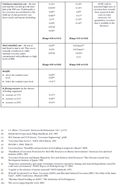
The corrosion rates for marine steels affected and unaffected by Accelerated Low Water Corrosion are shown below in a table taken from Ciria Report C634.
Where Can Accelerated Low Water Corrosion Be Found?
While the specific causes and interactions between factors are largely unknown, the following factors are thought to influence a sites predisposition to ALWC.
- Tidal Currents – the speed of tidal currents does not seem to influence the development of ALWC, though there is some evidence to suggest that high currents may reduce the risk.
- Tidal Range – A high tidal range may reduce the risk of Accelerated Low Water Corrosion occurring. Also the size of the zone in which ALWC occurs may be dependent on the tidal range of the site.
- Operations – There is some evidence that a high rate of traffic at a port site may increase the risk of ALWC occurring.
- Pollution – It is not clear how this relates to Accelerated Low Water Corrosion. There is some evidence that pollution from the fishing industry increases the risks, though ALWC has been found in clean marinas and can be reduced in areas of high water contamination.
- Sunlight – Sunlight may be a factor which could explain why Accelerated Low Water Corrosion tends not to occur in inpans or shaded areas. Sunlight may increase the risks and speed at which ALWC develops. There may also be an effect from the amount of UV which the steel is exposed to as UV is known to retard the development of bacteria.
- Age of Structures – There is reduced occurrence of ALWC on older structures, perhaps due to protective deposits which have had time to form before bacterial activity.
- Steel Grade – This does not appear to affect the occurrence of Accelerated Low Water Corrosion though some have suggested it may be more prevalent after the switch to cleaner steels in the 1970s.
Accelerated Low Water Corrosion is a global phenomenon and has been reported in all climactic conditions. It has been identified in Scandinavia, Belgium, Germany, Holland, France, USA, Canada, Zanzibar, South Africa, Australia, Cyprus, UAE, Japan and in the Southern Caribbean.
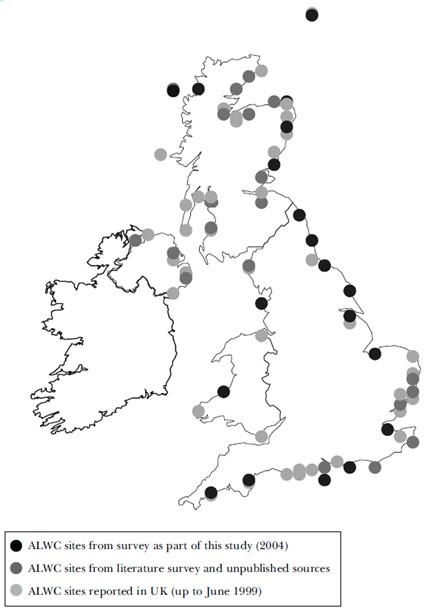
In the UK Accelerated Low Water Corrosion was first reported on the South coast and North Sea coasts. It has since been identified in Scotland and Northern Ireland. Surveys have suggested that around 13% of Ports and Harbours have some areas of ALWC, with around 4% of all sheet piled structures affected. A map showing the areas identified in surveys taken from Ciria Report C634 has been provided below. It is however expected that the occurrence of ALWC is much more widespread then indicated from survey responses.
Accelerated Low Water Corrosion Identification
Accelerated Low Water Corrosion identification can take place either during scheduled general inspections or inspections specifically organized for the purpose of checking for ALWC. This inspection must take place at a low spring tide so that the affected area will be clearly visible.
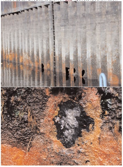
Accelerated Low Water Corrosion has a recognizable appearance, patches of lightly adhered bright orange and black (iron sulphide rich) deposits over a clean, shiny and pitted steel surface. As these pits deepen, a dishing effect is seen which eventually leads to a hole opening.
Accelerated Low Water Corrosion occurs only over narrow horizontal zones, generally just above LAT. There is often no perceived pattern in the distribution of ALWC, even among sites in close proximity with similar exposure conditions. Within structures it can also occur in clusters on parts of the structure while other areas remain unaffected.
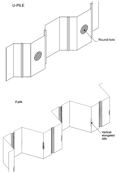
On Z piles the damage caused by Accelerated Low Water Corrosion tend to form vertical, elongated slits up to 1.0m long and 0.1m wide. These slits occur near to the corner or webs of the outpans. On U shaped or straight web piles the damage caused by ALWC typically forms round holes up to 300mm diameter on the outpans. On tubular or box type piles the damage tends to form on the seaward facing side of the pile. It remains unclear why ALWC causes damage to these areas while inpans are almost always unaffected. A diagram showing the typical corrosion damage effects is shown on the right, taken from Ciria Report C634.
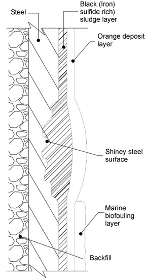
The surface deposits typically comprise of a two layered structure. A soft spongy bright orange outer layer overlies a thin, slimy, gelatinous inner black liquid or paste layer. The surface layer is not generally well adhered to the substrate steel and can usually be removed quite easily. This outer layer can sometimes be masked by marine growth such as algae, mussels, barnacles or seaweed. It is possible to take representative samples from the surface deposits for analysis to confirm the presence of SRB and sulfides.
The substrate steel is bright, clean and shiny which indicates active corrosion. There will be extensive pitting compared with surrounding areas. These pits will eventually start to overlap and produce a dishing effect which will eventually develop into a hole.
Photos of typical Accelerated Low Water Corrosion patches taken from Ciria Report C634 are shown below.
A diagram showing the typical corrosion composition is shown below, taken from Ciria Report C634.
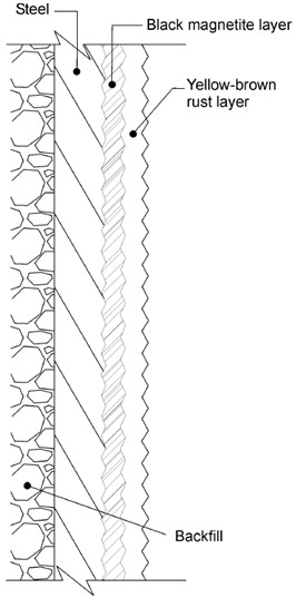
This differs from traditional steel corrosion which typically consists of an inner layer of black magnetite, a thin layer of its green hydrate and an outer coating of yellow-brown rust. This can vary considerably even over the same structure due to differences in steel composition, member geometry, surface condition, surface deposits and stresses or vibration. A diagram illustrating this is provided to the right, taken from Ciria Report C634.
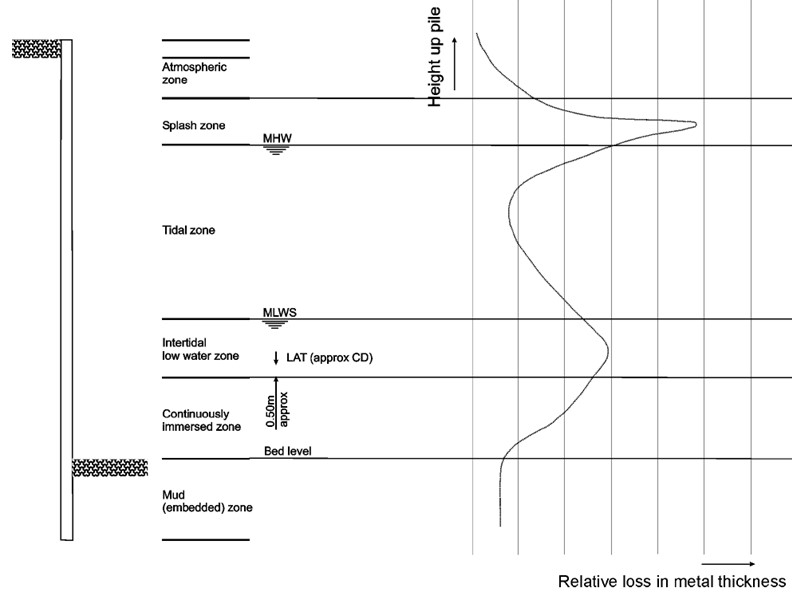
A typical corrosion profile for unprotected steel taken from Ciria Report C634 is shown below.
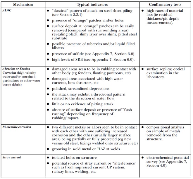
Localized or concentrated corrosion can also take place on steel marine structures for other reasons than Accelerated Low Water Corrosion. Some examples may come about due to;
- Differential concentration cells due to different exposure conditions at the steel surface
- Differential aeration conditions due to local differences in dissolved oxygen
- Crevice corrosion around narrow apertures
- Bimetallic corrosion where two metals are joined
- Erosion corrosion where protective surface deposits are regularly removed by wave or tidal actions or by the effects of ship thrusters
- Stray current corrosion where a current is flowing through the steel
- Other types of Microbially Influenced Corrosion (MIC)
A table taken from Ciria Report C634 showing the differences between Accelerated Low Water Corrosion and other common corrosion mechanisms is shown below.
Accelerated Low Water Corrosion Condition Surveys
First a visual survey of the structure at low water can be undertaken. Note that it is likely that if any ALWC affected areas are identified during a quick visual survey, there is a likelihood that several others may also be present below low water or out of sight.
If Accelerated Low Water Corrosion is identified or suspected, a detailed survey should be undertaken. This can be undertaken by divers or using a limpet dam.
As part of this detailed survey steel thickness measurements should be taken at all areas affected by ALWC. This will indicate the corrosion rate and from this an estimation of the structures remaining design life should be possible.
Before measuring the steel thickness the marine growth and surface deposits should be removed. It is recommended that only light techniques are used to remove the surface deposits to ensure that well adhered deposits which may offer some corrosion protection are not removed. Cleaning of the orange surface deposits should be easy by hand.
Measurements should also be taken of the steel thicknesses in areas which are not affected by Accelerated Low Water Corrosion. This will provide a useful baseline for comparison with the ALWC areas and provide the background corrosion rate. It will also show if other corrosion mechanisms are at work as well as ALWC.
The detailed survey should identify and mark all areas of the structure which are affected by Accelerated Low Water Corrosion. A photographic survey should be done to all areas of ALWC, both before and after any surface cleaning. Panoramic photos can be produced to show the whole surface of a steel sheet pile wall for example. This survey record can be used to plan and monitor repairs.
Where the structure inspected is particularly extensive, it may not be economical to inspect and measure all parts of the structure. In these cases a representative sample of components should be measured, ensuring that those most at risk are included.
An above ground survey is also useful for sheet pile structures. Any areas of settlement behind the wall may indicate the presence of a hole in the wall and the loss of some of the retained material.
Other potential measurements which could be taken during a detailed survey include electrochemical potential surveys, small diameter coring or samples of the surface deposits for laboratory analysis.
Following a detailed condition survey the results should be analyzed to assess the overall condition of the structure and whether any remedial works are required. This may include structural analysis to determine when and where remedial works are likely to be required.
A programme of regular monitoring inspections should be implemented to check for spread of the ALWC and to check that the corrosion rate does not increase. This can also be used to ensure that remedial works are done when needed.
Accelerated Low Water Corrosion Protection and Repairs
Once detailed inspections have been undertaken and the current condition and corrosion rates determined for the structure, next repairs and/or protective measures may be required. The severity and timing of the remedial works will be dependent on the detailed survey results. There are a number of potential actions, each of which is detailed in the following sections.
Structural Repairs
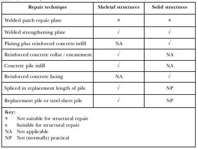
Structural repair may be required if the ALWC has been identified at a late stage and significant steel thinning or holing has already taken place. The following table taken from Ciria Report C634 gives an indication of which repair techniques may be applicable.
Welded Patch Repair Plates
This involves the installation of a repair plate shaped to match the cross section of the damaged section of pile. The plate should be sized to cover the area of thinned steel and be suitably thick to replace the missing steel and to resist any loadings, for example from retained material.
This generally means the plate will be at least 2.0m long and 10mm thick which will allow the plate to be suitably welded to sound parent steel. The maximum thickness of the plate will be determined by the ability to bend the steel to the required shape. For mild steel the maximum bend radius will be twice the plate thickness. Care should be taken that the plate is long enough to span over any corroded surfaces as these can be irregularly shaped and difficult to weld to. On steel sheet pile walls it is often useful to weld to clutches.
The parent steel is then jetted clean with 800 bar or similar water jetting equipment. Any voids behind a wall should be filled with a fast setting cementitious mortar or expanding foam. The plate is then fixed in place and the perimeter welded. A limpet dam is often used to allow the pile to be cleaned and welded in dry conditions. Incomplete or tack welding is not likely to be sufficient and can result in crevice corrosion. If welding is not suitable to the whole perimeter any gaps can be sealed with an epoxy based paste or cement grout.
An alternative to welding of the plate is to use mechanical fixings (nuts and bolts). The threaded studs of the bolts can be connected to the structure by either conventional or friction welding. Friction stud welding can be used to weld fasteners on the normal face both above and below low water with minimal surface preparation. Alternatively the studs can be fired into the steel with a bolt gun above and below low water, though care should be taken that the steel is thick enough.
This method is non-structural and is used to replace thinned sections and to seal existing holes to prevent ingress of water or loss of retained material.
This method can introduce bimetallic corrosion when the small new steel plate is attached to the large old steel structure. The materials for the plate and the welding consumables should be chosen carefully to minimize the risks of bimetallic corrosion. These effects can be mitigated by applying a cathodic protection system or coating either locally or to the whole structure. Alternatively some sacrificial steel thickness can be utilized for the plate or coatings or cathodic protection systems can be applied to the structure.
Care must be taken that critical components such as welds and fixings are not subject to preferential weld corrosion. This risk can be minimized with the careful choice of welding consumables. Maximum hardness values should be specified where impressed cathodic protection systems are to be used in order to minimize the risk of hydrogen induced stress cracking. Fixings bolts are usually fabricated from high strength low alloy steels which should be slightly cathodic to the adjacent mild steels and therefore should experience less corrosion.
Welded Strengthening Plates
This involves installing a steel plate to more heavily corroded areas where structural additional structural strength is required. The plate can be sized similarly to the patch repair plates described above but must be long enough to transfer loads from the pile into the plate, and then from the plate into the pile again bypassing the weakened area of pile.
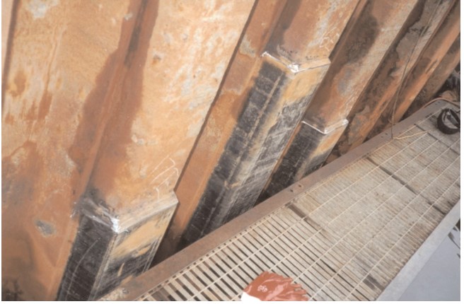
U shaped plates are often used to enclose damaged outpans on steel sheet pile walls. An example of this type of repair is shown below. Achieving the correct cross sectional profile can be difficult, particularly where piles have deformed during installation or are deflected under loading.
The installation procedure is again similar to the above patch repair though the welds will need to be structural in order to transfer the loads. It is often necessary to leave weld windows which are holes cut into the plate to permit sufficient stress transfer where the expected loads are large and there is insufficient plate perimeter without the weld windows.
The preparation of structural plates can be difficult due to the thickness of plate and the cross-sectional profile required.
Plating & Reinforced Concrete Infill
A similar method can be used to repair the inpans of sheet pile wall structures. Steel sheet pile structures can be repaired using this technique, particularly where the side and inpans are corroded as is common in Z piles.
The piles must first be cleaned of marine growth and corrosion product. A limpet dam can be used to do this in dry conditions. Steel reinforcing hoop bars are welded to the piles and to the back of a plate which is then welded to the outpans, spanning the inpans. Additional reinforcement can be added to the void where required. The bottom of the void is now sealed and the void filled with concrete.
This technique is not usually suitable for U piles because the outpans must be free of ALWC to accept the plate weld. For Z piles the plate is welded to the clutch which is usually unaffected by ALWC.
Insitu Reinforced Concrete Collars or Encasement
Isolated piles can be encased in concrete or grout to prevent further corrosion. This is done using grout bags, fiberglass formwork or temporary or permanent steel shuttering.
The piles should be cleaned with water jets to remove all marine growth and corrosion products. This will ensure adequate bond between the steel and the new concrete. Shear studs are also often welded onto the pile to ensure adequate load transfer.
The concrete or grout used should be of sufficient quality and cover to minimize the rate of chloride ingress reaching the reinforcement. Cathodic protection or corrosion resistant reinforcement can also be used.
The increased rigidity of the newly installed concrete can lead to cracking of the concrete, particularly where the structure is flexible such as for berthing and mooring dolphins. Any cracking would allow ingress of seawater and would lead to corrosion of the reinforcing steel and the steel pile.
Reinforced Concrete Facing
This method involves installing a new concrete facing to a steel sheet pile wall. Steel reinforcing bars are welded to the sheet piles and used to support the reinforcement. The face of the repair is now shuttered and the void infilled with concrete. This forms a continuous or partial concrete wall face which strengthens the wall and protects it from further corrosion.
Concrete Pile Infill
Concrete or grout can be installed to the void of a tubular or box pile to provide strengthening, particularly to buckling. However the load transfer mechanism from the pile to the concrete infill can be difficult to achieve.
Pile Splicing
It can sometimes be possible to cut out and remove a small section of pile then replace. However this is usually not possible and the spliced section may be subject to bimetallic corrosion.
Replacement Pile
In some cases, particularly where the existing pile is seriously damaged, it can be possible to install a pile adjacent to the existing pile a tie the new pile into the structure as a replacement for the existing. This can however be very difficult to achieve in practice and is often not possible unless a new alignment is used.
For sheet pile wall structures it is sometimes possible to install a new line of shorter steel sheet piles in front of the existing wall. This short wall is then tied into the existing wall which removes the need to install an entire new wall. Note that care must be taken to ensure that this new low wall does not become a hazard for shipping.
Access
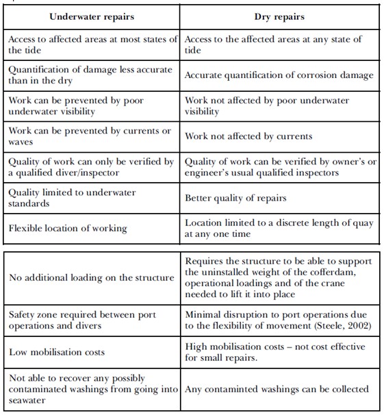
Whatever the method of repair, the location of the corrosion must be accessed which is difficult due to the location near low water. Generally the works can be accessed either using divers or in the dry using a limpet dam. A comparison of the two methods taken from Ciria Report C634 is shown below.
Underwater repairs undertaken by divers are usually economical for small scale repairs and can usually be undertaken to a good level of quality as long as the divers are suitably experienced and the visibility and environmental conditions are good.
Water jetting equipment can still be used underwater for cleaning and preparation of the steel structure. Welding underwater is possible using special underwater flux covered electrodes. Underwater welds will generally be inferior to welds undertaken in dry conditions and inspection can be difficult. For this reason structural welds are often difficult to achieve underwater.
Dry repairs can be undertaken using a limpet dam or similar equipment. These structures clamp onto individual piles or small sections of steel sheet piling which can then be drained to produce dry conditions. This provides better conditions for welding and allows the completed repairs to be inspected fully.
Accelerated Low Water Corrosion Protection Measures
For new structures likely to be at risk of Accelerated Low Water Corrosion or where ALWC has been identified at an early stage on an existing structure, there are a number of measures which can be taken to protect the structure from the effects of ALWC. It can be difficult to justify the large expense of a protection system when ALWC can be difficult to predict with any accuracy. In general a system should be chosen which protects the whole structure from general corrosion rather one which may protect local areas at significant risk of developing ALWC. In many cases it may be prudent to install a protection system a certain number of years after ALWC has been identified rather than take pre-emptive measures against ALWC which may not occur.
These protection strategies are typical measures taken to counter general corrosion and are detailed in the following section.
Corrosion Allowance
Additional thickness of steel is specified to allow for a higher expected rate of corrosion due to Accelerated Low Water Corrosion. This is not a practical solution for most new build projects as this would significantly increase the costs of construction as heavier steel would be applied to the whole pile to counteract a small area where ALWC will be active.
Additional thickness allowances should however be applied to patch repairs where no further corrosion protection measures are to be taken.
Steel Grade
Using a higher strength steel is unlikely to deter ALWC from becoming active but can provide a greater factor of safety and therefore greater tolerance for corrosion. However this is often impractical for similar reasons to the above, unless the components at risk from ALWC are small and can be isolated. This would also not delay the formation of holes in sheet piles as the steel would degrade at the same rate, and the greater deflection of very thin high strength steels under load should also be considered.
Mild steels should generally be specified for repairs as they are more electrochemically compatible with the structure than higher strength steels. Mild steels are also generally easier to bend to shape and to weld than higher strength steels.
Welded Patch Plates
The section thickess in low water zones at risk of Accelerated Low Water Corrosion could be increased by welding steel patch plates to these sections even before ALWC has been identified. This can be easily done before the piles are installed though care needs to be taken that this will not cause problems during piling. There would also be problems if the piles needed to be installed higher or lower than expected due to obstructions or site conditions.
This method also requires assumptions to be made about the expected zone of ALWC and the expected rate of corrosion which may be very high.
Structural Modifications
In some cases it may be possible to relocate any zones of maximum stress away from the low water zone which will increase the life of the wall if subjected to ALWC. This can sometimes be achieved by simply moving the position of walings and anchorage systems installed with steel sheet pile walls. This will not protect against holing of steel sheet pile walls however and the loss of retaining material.
Paint Coatings
Coatings can be used for the whole structure or for just the low water zone to prevent Accelerated Low Water Corrosion. Coating systems are not suitable for areas subject to mechanical damage or abrasion which would remove the coating over time. If coatings are installed before the piles are driven there will usually be some damage to the coating during installation. Coatings can be installed after installation but they are usually of inferior quality due to problems with surface preparation and possible underwater application.
Metallic Coatings
Aluminum or zinc coatings can be applied, sometimes with a paint coat installed on top to provide additional protection. These are not practical to install to existing structures but can be effective when specified before installation.
Wrappings
Tape wrappings can also be used to protect vulnerable areas such as low water zones, particularly for tubular piles. They are not usually specified for new structures, but are often used in conjunction with repairs. It can however be difficult to ascertain the effectiveness of the wrapping after installation.
Cathodic Protection
Cathodic protection will provide almost complete protection from all forms of corrosion, including Accelerated Low Water Corrosion. Installation of cathodic protection systems on existing structures will halt the progress of ALWC. The orange surface deposits are often removed naturally when the steel is polarized at the start of the cathodic protections design life. Cathodic protection systems can be designed using a spreadsheet program such as the CivilWeb Cathodic Protection Design Spreadsheet.
The recommended actions to prevent or halt ALWC is a combination of coatings and cathodic protection.
