The loads on buried pipes can be determined in the same way for rigid and flexible pipes. Indeed there are a number of external loadings which can be calculated in the same way for both pipe types.
Internal Water Load on Buried Pipes (Ww)
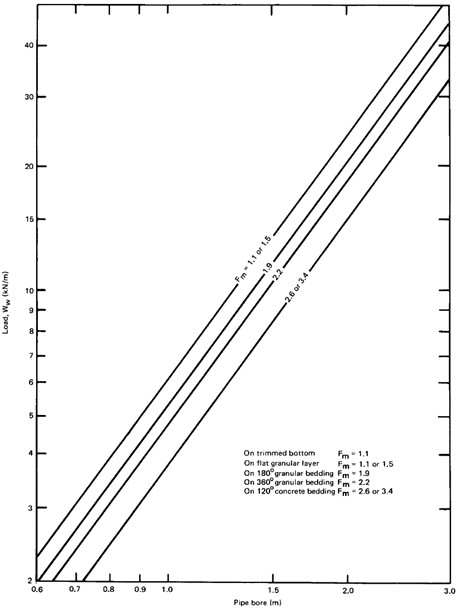
The water present inside a drainage pipe exerts a load on the pipe ring and supporting soils and bedding material. This internal water load has very often been neglected in traditional design charts and tables due to the relatively small impact except for particularly large pipes with small fill heights. However as this load can be calculated quite simply the CivilWeb Buried Pipe Design spreadsheet includes the weight of internal water load in all its calculations. The average water load for various pipe sizes is shown in the chart below.
The load imparted by the contents of the pipe is not equal to the total weight of the water, it must be modified by an equivalent water load factor dependent on the bedding type as shown in the below equation.
Density of Water (p)
The density of water in a drainage system can be taken as 1,000kg/m3.
Internal Diameter of Pipe (D)
This is the internal diameter of the pipe used to calculate the total volume of water.
Acceleration Due to Gravity
This can generally be taken as 9.81m/s2.
Water Load Coefficient (Cw)
The water load coefficient adjusts the total weigh of the water to allow for the different actions on different bedding types. This has often been taken as an averaged 0.75, but more accurate values are shown in the table below.
Imposed Loads on Buried Pipes – Highway Loadings
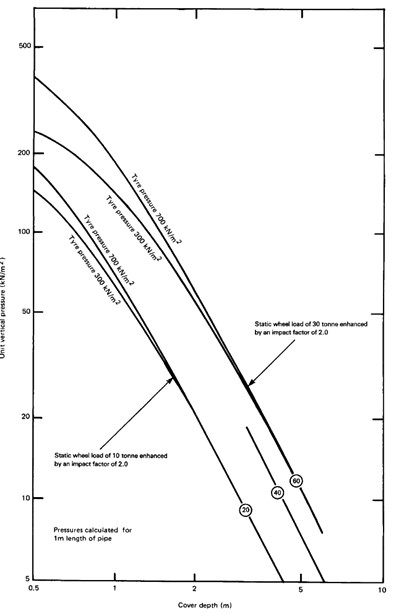
Probably the most common live imposed load on a drainage pipe is the loading from vehicles on a road above the pipe. These loadings are calculated as a series of concentrated wheel loads acting on the pipe at the same time. As this is such a common design parameter many tables and graphs of standard highway loading models have been published.
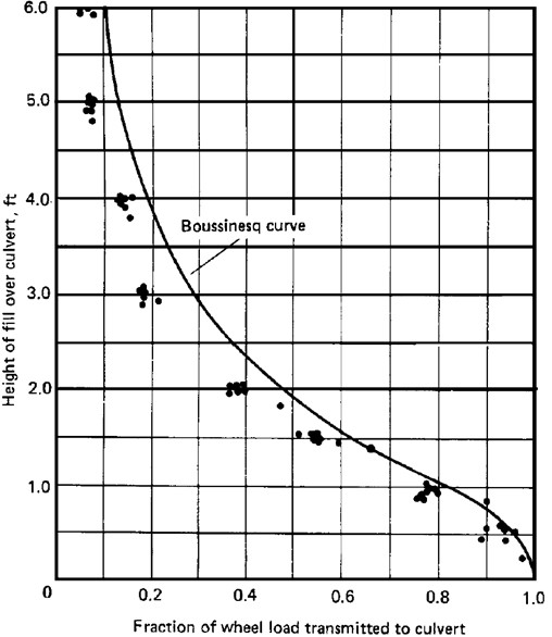
Concentrated loadings such as wheel loads from vehicles are determined using the Boussinesq theory model for vertical stresses caused by concentrated loads on a semi-infinite elastic homogenous layer. This is presented in detail below. The simplifications in the Boussinesq theory model are deemed to be either not significant or conservative such as omitting the stiff road surface in the calculations. This method has proved adequate in practice over many years. Experimental data has confirmed the suitability of the Boussinesq model as shown in the graph below.
The peak pressure directly over the pipe is calculated and then the pressures at 0.5m either side are used to determine an average pressure over a 1.0m long section of pipe. This is repeated for all applicable wheel loads to determine the total pressure from the vehicle per metre run of pipe.
Highway loading in the UK is split into three broad categories;
- Main Road Loading – This is the heaviest loading which the pipe can expect if laid beneath any major highway in the UK. This loading category tends to stick to the old BS 5400-2 loadings as most published tables where compiled when this was still active and these loadings are considered to be conservative compared to the more recent standards.
This loading condition is designed for all major roadways and for any minor roadways where heavy traffic may be diverted. Generally this is taken as roads expected to carry at least 200 commercial vehicles per day in each direction.
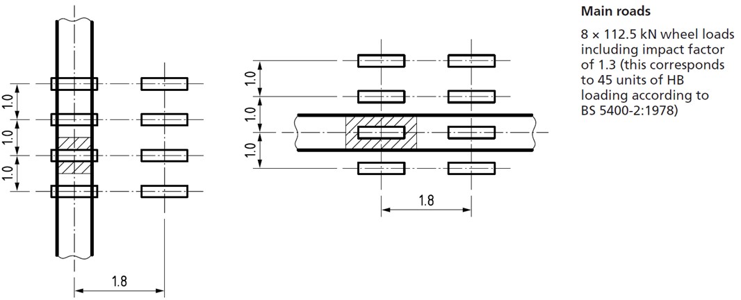
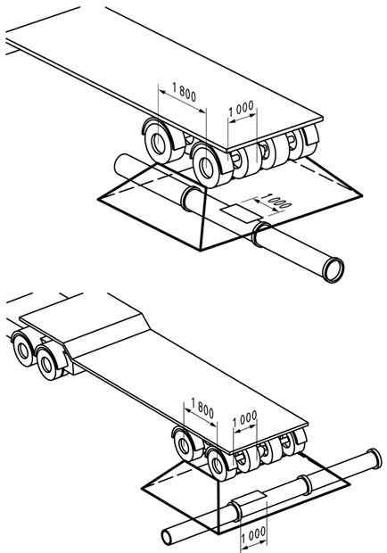
This loading assumes a worst case with two heavy goods vehicles passing over the pipe at the same time, one in each direction or one in each lane of a dual carriageway. This loading consists of 8 concentrated wheel loads of 112.5kN each (this includes an impact factor of 1.3). Each wheel load is assumed to have a contact area at an effective tyre pressure of 1,100kN/m2. The loading arrangement is shown in the below diagram taken from BS 9295.
- Light Road Loading – This is for lightly trafficked roads where heavy vehicles are unlikely to regularly run over the pipe. This loading category is to be used for any roadway which does not meet the requirements for main road loading, ie minor roads carrying less than 200 commercial vehicles per day in each direction and where heavy traffic is unlikely ever to be diverted onto the road.
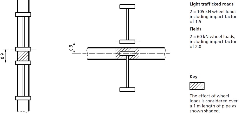
This load category assumes two smaller lighter goods vehicles running over the pipe at the same time. This consists of 2 wheel loads of 105kN each (this includes an impact factor of 2.0). Each wheel load is assumed to have a contact area at an effective tyre pressure of 700kN/m2. The loading arrangement is shown in the below diagram taken from BS 9295.
- Field Loading – This load category is for pipes underneath fields which may be loaded occasionally by farm vehicles or equipment and for lightly trafficked access tracks. This load category also is deemed suitable to cover any surcharge loadings from small heaps or stacks of materials placed on the surface above the pipe. Any large surcharge loads must be designed specifically using the procedure outlined in the surcharge loading section of this document.
This load category assumes two wheel loads of 60kN (which includes an impact factor of 2.0). Each wheel load is assumed to have a contact area at an effective tyre pressure of 400kN/m2. The loading arrangement is shown in the previous diagram taken from BS 9295.
Note that future upgrading or widening of roads should be taken into account when determining the loading category. Pipes under road verges should usually be designed as if they were under the road for this reason. Any special plant or equipment using non-highway roads should be designed specifically using the procedure outlined in the concentrated loading section of this document.
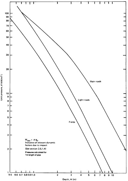
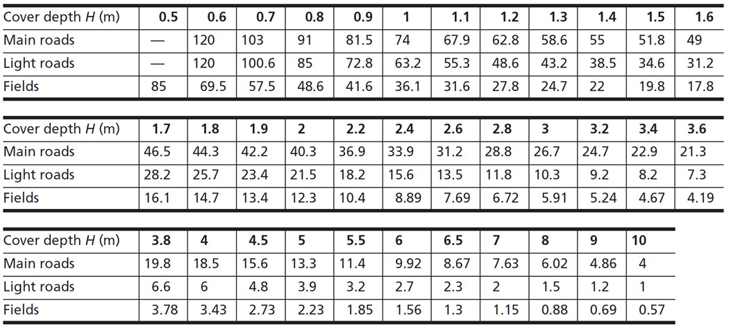
The above loadings have been published as both graphs and tables for ease of use, as shown below.
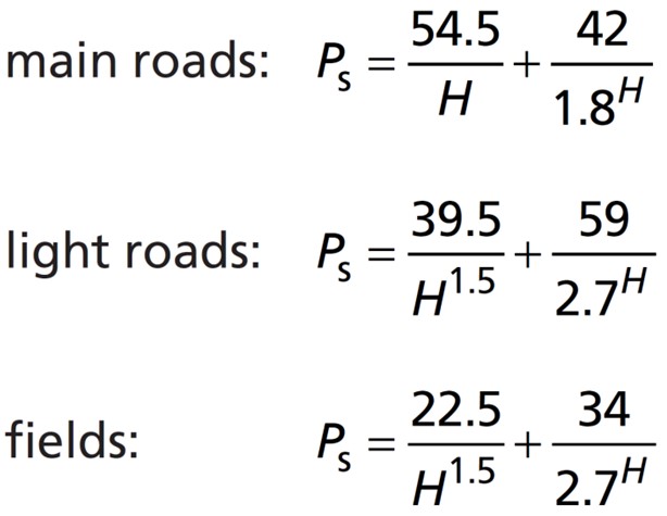
The CivilWeb Buried Pipe Design spreadsheet calculates the loadings from three approximate equations given in BS 9295 derived from the tabulated data as shown below. Note these equations have been adjusted in the spreadsheet to match the tabulated values more closely, reducing the error from up to 5.4% to around 0.1%.
Only standard highway loadings are included in the main CivilWeb Buried Pipe Design spreadsheet. However the spreadsheet does allow the user to override these standard highway values if a more appropriate surcharge loading condition is known to the designer. Separate surcharge pressure calculation tools are included with the CivilWeb Buried Pipe Design spreadsheet package for concentrated loads and uniform surcharge loads.
The average surcharge pressure (Ps) is then multiplied by the outside pipe diameter (Bc) to calculate the total surcharge load (Wcsu).
Imposed Loads on Buried Pipes – Concentrated Point Loadings
Concentrated point loads on buried pipes other than from standard highway traffic can also load the pipe. This could be from non-standard highway plant and equipment operating in a particular area or from other foundations or structures loading the ground above a drainage pipe.
A simplified version of the Boussinesq equation is generally used for calculation of stresses acting on pipes from concentrated live loads on the ground surface. This equation is presented below where P is the point surcharge load, H is the depth to the pipe crown and r is the horizontal distance from the load to the pipe centre.
The CivilWeb Buried Pipe Design spreadsheet includes a calculation tool for estimating the vertical pressure acting on a pipe from up to 16 concentrated point loads on the surface. This is designed so that the designer can accurately model any likely combination of plant and equipment which may load the pipe. Note that while this tool does calculate the average pressure for a 1m long section of pipe, the designer may need to try several different potential locations to determine the worst case loading scenario.
Imposed Loads on Buried Pipes – Uniformly Distributed Surcharge Loads
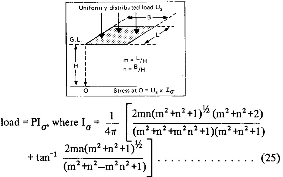
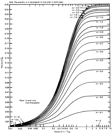
The effects of uniformly distributed surcharge loads of small extent on buried pipes can also be determined using the Boussinesq Equation. Surcharge loads such as heavy tracked vehicles or outrigger loads can be modelled using this method. The following equation is used to calculate the stress caused below the corners of a rectangular loaded area as shown in the diagram below.
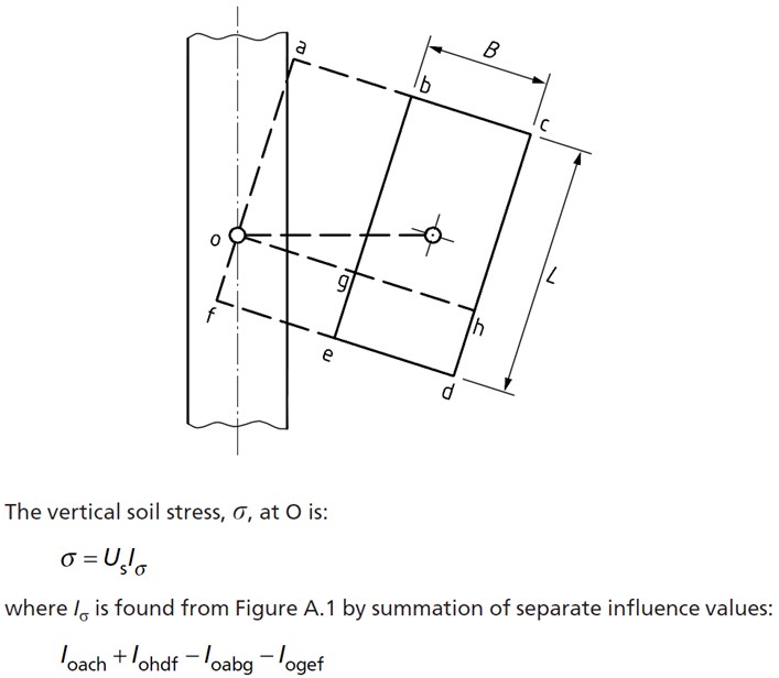
For movable surcharge loads such as vehicle tracks the worst case is usually where the centroid of the load is over the centre of the pipe. In this case the loaded area is simply quartered and then the result multiplied by four. Where the loaded area is fixed and offset from the centre of the pipe the resultant stress must be determined from summation of a number of imaginary loaded rectangles as demonstrated in the below diagram taken from BS 9295.
Note that the extents of this surcharge load must be small, if both of the loaded area dimensions are too high compared with the cover depth the equation will break down and return negative values. The equation is usually suitable for most vehicle or foundation loads, unless the cover depth is small. In this case the cover depth can be increased and the equation will return to accuracy.
The CivilWeb Buried Pipe Design spreadsheet includes a tool for calculating the surcharge pressure from small uniformly distributed surcharges centered over the pipe. Offset surcharges can be calculated with the same tool used to calculate all the required rectangles, then added together by hand.
Imposed Loads on Buried Pipes – Uniformly Distributed Surcharges of Large Extents
Large uniformly distributed surcharge loads on buried pipes can be modelled by increasing the effective depth of the cover above the pipe. The additional cover depth will depend on the magnitude of the surcharge load and the unit weight of the soil. Where the surcharge is given in kN/m2 and the unit weight of the soil in kN/m3, the effective additional height of cover will be the surcharge magnitude divided by the unit weight of the soil.
The CivilWeb Buried Pipe Design spreadsheet includes this method of calculating the effects of large surcharges on the pipe. Note that this increased effective depth is not included when calculating the surcharge loads from vehicle loading.
Construction Loads on Buried Pipes
Loads on buried pipes during construction can often be the critical design condition. This can be either because the cover over the pipe will be reduced or increased at certain times during the construction or because the construction plant will be larger than anything encountered during the pipes service life.
To prevent the pipes from becoming damaged during construction either the increased loads must be accommodated in the pipe design (at least in small sections of the pipe for plant crossing areas), or the contractor must be informed of the maximum allowable loadings on the pipe and alter their methods or provide protection to the pipe to suit.
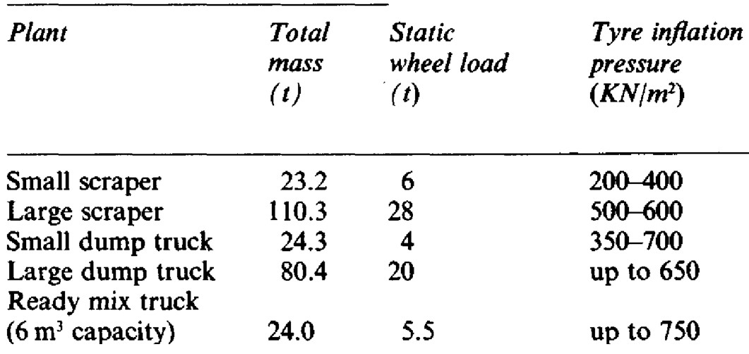
Construction loads can be modelled using the concentrated point load calculator included within the CivilWeb Buried Pipe Design spreadsheet. Some typical plant details are shown in the table below. A graph showing the loads imposed by some typical construction plant types are included below, with some tabulated values.
Rail Loads on Buried Pipes
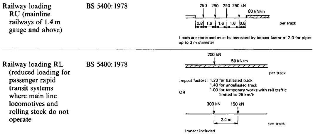
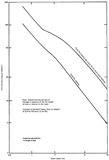
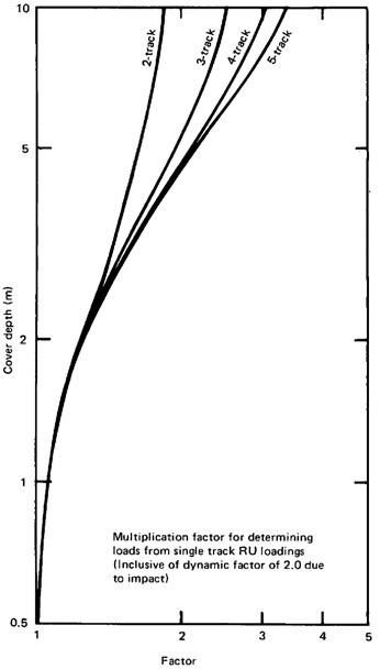
Rail loads on buried pipes should be considered in accordance with BS 5400-2. This includes two classes of loading, RU which includes for heavy loads as per the main network and RL which includes lighter loads expected from passenger trains only on rapid transit networks where main line freight trains cannot go. The loading arrangements are shown in the below diagrams with graphs showing the loadings and a multiplier for multiple track arrangements on subsequent pages.
Get your copy of the CivilWeb Buried Pipe Design spreadsheet including full rigid, semi-rigid and flexbile pipe design now for only £20.
Or why not bundle the CivilWeb Buried Pipe Design spreadsheet with our Pipe Flow Calculator for only £5 extra?
Or save £50 by buying our full Drainage Design Suite including all our drainage design spreadsheets.
Download Free Trial Version
To try out a fully functional free trail version of this software, please Click Here or enter your email address below to sign up to our newsletter.
