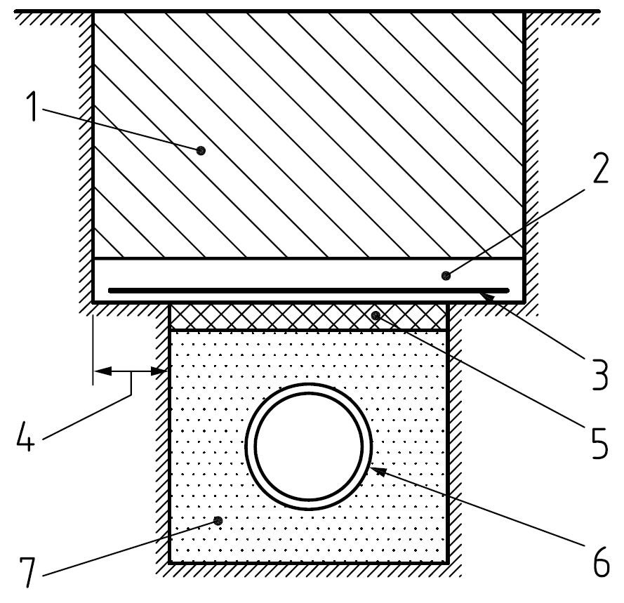
As the concrete protection slab is a common solution to shallow pipes, there are a number of standard pipe protection slab details which have been published which illustrate the requirements. The below pipe protection slab detail taken from BS 9295 can be used to explain the general design requirements.
The CivilWeb Concrete Protection Slab Design Spreadsheet can be used to design concrete protection slabs for pipelines and other vulnerable services. The spreadsheet assumes that the concrete protection slab being designed abides by the below detail principles. If installed correctly, these pipe protection slab details will ensure that the pipe protection slab will perform as designed.
Pipe Protection Slab Details
- Pipe Backfill – The backfill on top of the pipe must be suitable backfill material, similar to that used for any normal pipe installation. The depth of backfill on top of the concrete protection slab will affect the pipeline protection slab design as the dead load of the backfill will act as a uniformly distributed load on the concrete protection slab.
- Pipe Protection Slab – The concrete protection slab should be made of a minimum of C20 strength concrete and should be sufficiently thick to handle the forces applied to it from the backfill material and imposed surface loads. The thickness will sometimes depend on the depth of the pipe and will be a trade off with the reinforcement requirements (a thicker slab will require less steel). Generally the strength of the concrete mix used has little impact on the required thickness of the utility protection slab. In many cases a concrete blinding layer of 50mm is installed below the pipeline protection slab. This layer is not included in the concrete protection slab thickness for the structural design. Where the utility protection slab is used to protect gas pipelines or other potentially hazardous pipelines, hazard marker tape can be installed on top of the pipe protection slab to warn any future excavation teams of the purpose of the slab.
- Concrete Protection Slab Reinforcement – The pipeline protection slab detail will require steel reinforcement to the bottom of the concrete protection slab to resist the tensile forces imparted on the slab by the loadings above. As described above the amount of reinforcement is related to the thickness of the pipe protection slab. Where a standard reinforcement mesh is proposed such as an A393, the CivilWeb Concrete Protection Slab Design spreadsheet can be used to increase the thickness of the slab until the mesh reinforcement is adequate.The cover to the reinforcement should be at least 50mm, in some cases more where potentially aggressive soil conditions are found.
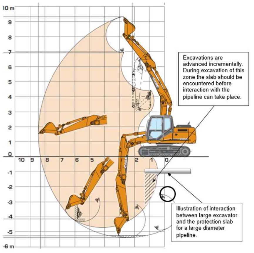
- Pipe Protection Slab Bearing Area – This is the ledge of existing ground on which the concrete protection slab rests. This ledge must be at least 300mm on either side of the trench in order for the pipe protection slab to safely span the width of the trench. This may need to be extended further in poor ground conditions as this ground will be expected to take the imposed loads. A CBR value of around 4% is generally acceptable. Where poor quality material is found this can be replaced with granular fill material. Where the pipe protection slab detail is designed to prevent accidental damage from excavators, the concrete protection slab should extend at least 1.0m from the outside of the pipe. This will prevent any excavation equipment from striking the pipe without going through the protection slab first. A diagram illustrating this is shown on below.
- Compressible Material – A layer of compressible material is required beneath the pipeline protection slab and above the granular bedding material. This allows the concrete protection slab to deflect slightly under loading as it would if there were a void beneath it, without the problems associated with a void. It also prevents the protection slab deflection from introducing any load directly onto the pipe. This layer of compressible material should be at least 75mm thick. This compressible layer can be achieved by installing expanded polystyrene. It should ideally extend the full width of the trench but must be at least 1.5 times the pipe diameter. The compressible layer must be directly below the concrete protection slab, it should interrupt any concrete blinding layers.
- Pipe – This is the pipeline being protected by the pipe protection slab detail. This should be installed as a normal buried pipe.
- Pipe Bedding – The pipe bedding should be a granular pipe bedding similar to that used for a normal pipe installation. There should be a minimum of around 150mm between the pipe crown and the underside of the pipeline protection slab.
Get your copy of the CivilWeb Concrete Protection Slab Design spreadsheet including now for only £20.
Or why not bundle with the CivilWeb Buried Pipe Design spreadsheet for only £5 extra?
Or save £50 by buying our full Drainage Design Suite including all our drainage design spreadsheets.
Download Free Trial Version
To try out a fully functional free trial version of this software, please Click Here or enter your email address below to sign up to our newsletter.
