The required french drain width depends on the width required to install the perforated pipe and on the volume of runoff water the trench will be required to convey to the perforated pipe.
French Drain Minimum Width
There are a number of guidance documents which specify a minimum trench width for the installation of drainage pipes. The most commonly applied is BS EN 1610. These minimum trench widths are designed to enable the pipe to be correctly and safely installed and to ensure that a suitable thickness of bedding material can be installed and compacted to the sides of the pipe.
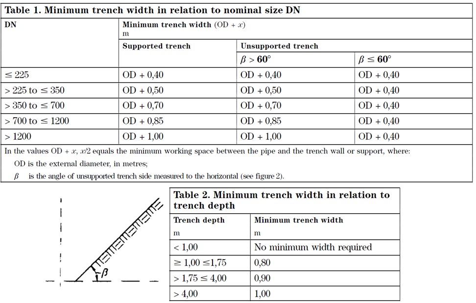
The trench width chosen by the designer must allow the pipe to be safely installed using the methods anticipated. Trenches may be vertically sided or V sided and can include supports such as sheet piles. The trench must be wide enough for the pipe with sufficient space at the sides for laying of the pipe, installation of any joints and for the placing and compaction of the filter material to the sides of the pipe. Minimum values for trench width are specified in BS EN 1610 and are shown below. The CivilWeb French Drain Design Spreadsheet includes a tool to check that the trench width specified is above the minimum value as specified in BS EN 1610. These minimum values can be amended where automated pipe laying systems are to be used where there will never be any people in the trench or between the pipe and the trench wall.
This is important for the structural performance of the pipe and is applicable to perforated pipes as much as to traditional drainage pipes. French drain perforated pipes tend to be very small in diameter and made flexible of flexible plastic materials. While the small diameter of the perforated pipe and the nature of french drains makes it unlikely that the pipe will be required to resist any significant loads, the flexible nature of plastic pipes means that the structural performance of the pipe is closely related to the thickness, quality and compaction of the material installed to either side of the pipe.
This is because plastic pipes will begin to deform under relatively small loads, maybe even just due the weight of french drain filter material on top of the pipe. As the pipe deforms it begins to take on a slightly oval shape. This deformation effectively loads the bedding material to either side of the pipe which provide a reaction force which maintains the shape and integrity of the pipe.
So traditional french drain widths should be largely in line with the minimum trench width requirements for drainage pipes as specified in BS EN 1610. A handy minimum trench width calculator tool is included for free with the CivilWeb French Drain Design spreadsheet.
French Drain Width – Hydraulic Design
The french drain width also impacts upon the hydraulic design of the french drain system. The french drain can only transmit a certain rate of runoff through the filter material and into the perforated pipe. This rate of percolation is related to the permeability of the filter material and the width of the french drain.
Rate of Flow Through the Filter Material
Firstly the rate of flow of water into the french drain through the overlying stone filter material must be determined. There is only so much water which can flow through the overlying soils at any particular time and this must be checked that it is sufficient for the drainage of the catchment. Otherwise the area above the french drain will flood as the water cannot get into the drain quickly enough.
The flow capacity of the overlying stone filter material (Q) can be estimated using Darcy’s Law as shown in the below equation;
Cross Sectional Flow Area (A) m2
This is the cross sectional area (length of drain x width of stone layer) of the stone layer through which water is flowing. In most cases the length of the french drain is known as it will follow a road or facility boundary. If the flow rate through the filter material is critical it is usually the trench width which must be widened or a more permeable filter material used.
It should be noted that in most cases the flow through the filter material will be much higher than the flow rate required. In these cases the designer may be tempted to optimize the design by specifying a narrower trench. While this is usually acceptable in relation to the hydraulic design criteria, there are minimum widths specified in BS EN 1610 which relate to the laying of pipes. These minimum trench width values depend on the method of installation and on the pipe depth.
Coefficient of Permeability of Stone (k) m/s
This is the permeability of the stone layer. Typical values of between 1.0m/s and 2.5m/s are often used for Type B filter material. This may be much lower if graded sand, topsoil or another material are used as either topping or filter material.
Hydraulic Gradient (i) m/m
This is the hydraulic gradient of the flow. In this case the hydraulic gradient of water flowing vertically over short distance can be taken as 1.
The rate of flow through the overlying stone layers should be checked that it is sufficiently large to accommodate the design storm otherwise the surface of the french drain will flood. In the vast majority of french drain cases the width of trench required to install the pipe is more than adequate. Only in exceptional cases where large areas drain into short lengths of french drain would this be a critical design check.
Filter Material Infiltration Rate
The rate at which water can percolate through the filter material is a critical design condition. The runoff water must be able to percolate quickly enough through the filter material or the area above the french drain will flood. Typical permeability rates achieved through coarse graded aggregates is between 2.5m/s and 3.5m/s.
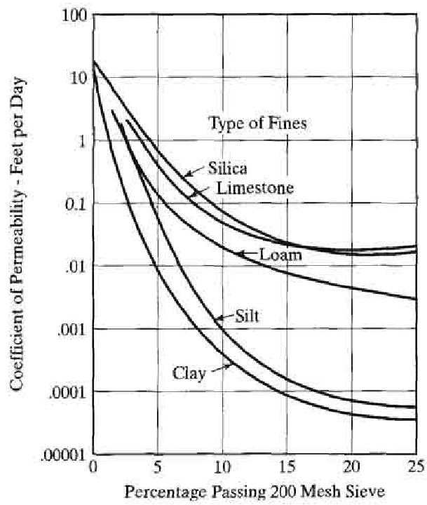
In most cases the filter material will be a coarse material chosen partly for its rate of infiltration. In order to maintain a suitable infiltration rate the filter material should consist of a well graded sand or gravel. The inclusion of fine particles in the filter material will lead to a decrease in permeability and in the strength of the layer. Removing the fines can however reduce the stability of the filter material so a balance has to be maintained between permeability and stability. The effects on permeability from fine particle content is illustrated in the below graph. In some cases a 5% fines content can reduce the permeability by up to 95% depending on the grading of the material.
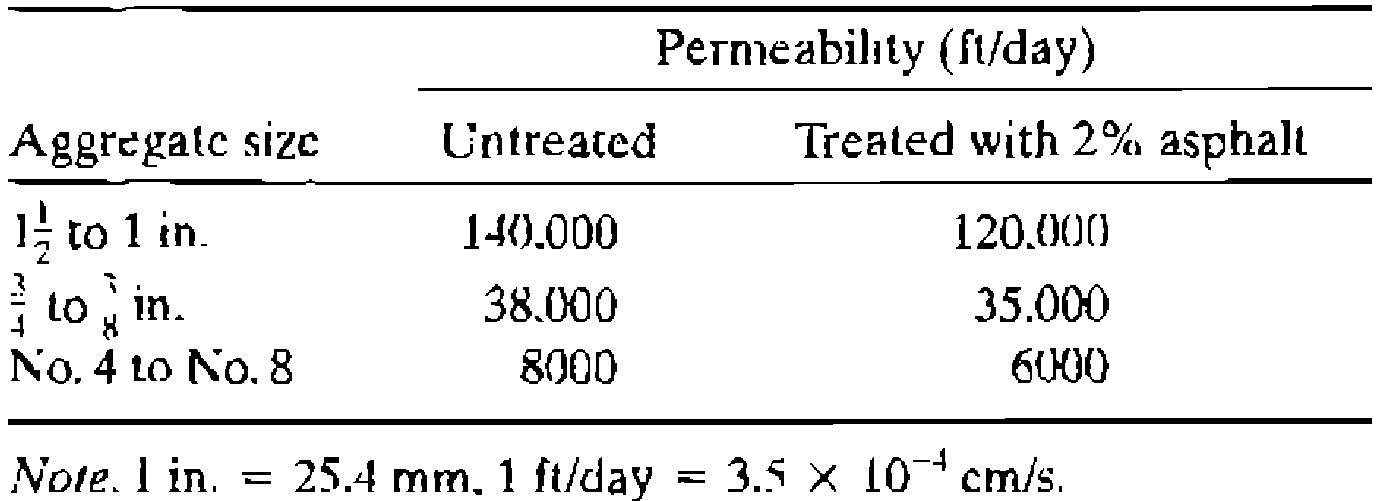
Alternatively the filter material can be stabilized by another method such as with bituminous or cementitious materials. Stabilization of filter materials tends to have only a small effect on the permeability, as can be seen in the below table. Stabilization also reduces the likelihood of stone scatter where french drains are damaged by vehicles accidentally running over them.
The selection of filter material will always be a balance between permeability and stability. The required permeability will be known from the hydrological analysis. This required permeability can then be used to design a filter material as stable as possible while fulfilling the required infiltration rate.
The infiltration rate which can be expected from a particular filter material can be taken from the supplier. Where this information is not available the permeability can be estimated from the following equation developed by Moulton where k is the permeability (ft/day), D10 is the effective grain size or the size at 10% of the material is passing, P200 is the percentage of material passing the number 200 sieve and n is the porosity.
The porosity can in turn be estimated from the dry unit weight (γd) (pcf) and the specific gravity (Gs) using the below formula. Note that this equation does not work for materials with no fines passing the number 200 sieve.
A typical value of around 0.5mm/s is often used for granular sub-base. A filter material permeability estimation tool is included with the CivilWeb French Drain Design Spreadsheet. Note that the insitu permeability of the filter material should be checked with a saturated hydraulic conductivity test undertaken in accordance with BS EN ISO 22282-5. Alternatively a laboratory test such as ASTM F1815 can be undertaken before the material arrives onsite if large quantities of filter material are to be used.
In most cases with traditionally installed french drains with a width of greater than 600mm and open graded filter materials, this width is not critical. It can become critical if the french drain is installed at a very narrow width or if a much less permeable filter material is specified. This may be because of water quality concerns or simply due to the availability of suitable filter materials.
Fin Drains and Narrow French Drains
Fin drains and narrow french drains are often used where there is a restriction on the french drain trench width. This restriction can be for either construction related issues or to minimize the french drain width when in operation.
Fin drains are largely prefabricated units which can be installed hard against one of the trench sides with very little space on the other. They are typically installed by machine removing the need for the french drain trench to include additional space for installation. The geocomposite material which forms the inlet to the pipe includes an extremely high permeability which removes the need for wide trenches to convey rainfall runoff. This allows them to be installed in very narrow trenches.
Get your copy of the CivilWeb French Drain Design spreadsheet now for only £20.
Or why not bundle with the CivilWeb Soakaway Design spreadsheet for only £5 extra?
Or save £50 by buying our full Drainage Design Suite including all our drainage design spreadsheets.
Download Free Trial Version
To try out a fully functional free trial version of this software, please Click Here or enter your email address below to sign up to our newsletter.
