It is often economic to design structures with both non-metallic coatings and cathodic protection systems for corrosion protection. The coating will effectively reduce the current demand from the structure in the same way as reducing the exposed area of steel.
The CivilWeb Cathodic Protection Design Spreadsheet allows the designer to include a coating system working alongside the cathodic protection system. The spreadsheet allows the design to specify coating breakdown factors for both immersed and buried parts of the structure. The designer then specifies a coating depletion rate and the spreadsheet alters the expected current demand from the structure to suit these values. For the anode design the coatings will protect the structure most in the initial phase making the final phase critical in most cases.
Coatings
This is particularly useful in the following situations;
- For structures with long design lives
- Where replacement of anodes would not be practical
- For weight sensitive structures where anodes designed for the full design life of the structure would be too large
- Where the current demand is expected to be high, such as in deep water applications where the formation of calcareous deposits may be slow
- Where certain components are shielded from cathodic protection due to their geometry
- Where only a certain amount of anodic material can be attached to the structure
Note that coatings are not recommended for components or parts of structures which require regular inspections, such as for fatigue cracking.
Metallic coatings are compatible with cathodic protection systems, though they do not afford any advantages in decreasing the current demand of the structure.
Where damage is done to the organic coating, the exposed steelwork will be polarized by the cathodic protection and therefore will be protected from corrosion. However, this polarization will produce alkali which can result in the cathodic disbandment of the surrounding coatings. For this reason oleo-resinous or alkyd coatings are not recommended for use with cathodic protection systems.
The coating can pick up moisture due to electro-osmosis as the liquid electrolyte passes through pores in the coating due to the potential difference. Water inside blisters in the coating will become alkaline due to the cathodic reaction and therefore corrosion will be hindered. The adhesion of the coating can also be affected by hydrogen evolution and by the production of chlorine in some conditions. The choice of coating is important and the coatings resistance to cathodic disbondment should be checked prior to being specified. This test can be undertaken using the procedure in ASTM G8.
Coating Breakdown Factors
Where coatings are used the current demand drops dramatically compared to bare steel, then slowly rises as the coating system deteriorates. The initial current demand and rate of increase can be estimated using coating breakdown factors. The coating breakdown factor is a function of the coating properties and its likely degradation over time. Note that this factor is not the same as the visual degradation of a coating system. A coating with extensive blistering can still electrically isolate the structure very well, while an unblemished coating may not.
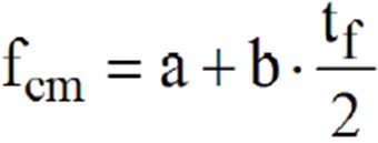
Guidance in DNVGL-RP-B401 advises that the coating breakdown factor can be estimated using the following equation where t is the coating age and a and b are constants dependent on the coating properties and the environment;
The factors a and b can be taken from the coating manufacturer or from practical experience from similar structures. Where this information is unavailable, further guidance is given in DNVGL-RP-B401 regarding the estimation of factors a and b. The coating must first be given a coating category, as defined below.
Category I – One layer of epoxy paint coating, min 20 μm nominal DFT. This includes shop primer coatings.
Category II – One or more layers of marine paint coating, min 250 μm total nominal DFT.
Category III – Two or more layers of marine paint coating, min 350 μm total nominal DFT. Note that Norsok M-501 systems no. 3B and 7 meet the requirements for category III.
For marine paint systems suitable for categories II and III testing and recorded performance in service should be provided. Marine paints can be epoxy, polyurethane or vinyl based. Coating work should always be completed in accordance with the manufacturer’s recommendations and surface preparation works such as blast cleaning should have prepared the surface to a minimum of SA 2.5 in accordance with ISO 8501.
When a coating category is determined, the factors a and b can be taken from the below table;
Note that structures above 30m depth are more exposed to both marine growth and wave actions which can accelerate the coating breakdown process. For flooded compartments of structures or closed compartments with free access to air, the values for >30m are applicable.
The values presented above do not account for significant damage to paint coating systems incurred during fabrication or installation. If damage is anticipated such as with driven piles, the damage should be estimated and accounted for in the design as a percentage of bare steel.
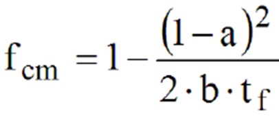
The mean and final coating breakdown factors are required for the design of cathodic protection systems. The mean coating breakdown factor is used to calculate the current demand for the maintenance period, and can be estimated using the below equation where tf is the design life of the cathodic protection system;
Where the design life of the cathodic protection system exceeds the calculated life of the coating system, the following equation should be used;
The final coating breakdown factor is used in the calculation of the final current demand, and can be estimated using the below equation;
If the calculated value of fcf exceeds 1.0, then 1.0 should be used.
There are several other methods included in other national and international standards, but as performance data of coatings on cathodically protected structures are rare, particularly for long service lives, the DNVGL-RP-B401 method is seen as a reasonable and conservative method of estimating the coating breakdown factors where better information is unavailable.
Cathodic Protection Design Spreadsheet
The CivilWeb Cathodic Protection Design spreadsheet uses a simpler but equivalent method as defined in BS EN 13174. In this method an initial coating breakdown value is specified for immersed and buried components and a simple depletion rate for the coating system is specified. These values are combined and used to estimate the current demand for the initial, final and maintenance design periods.
Typical values for these factors are given in BS EN 13174;
- Initial coating breakdown factors for immersed areas – 1% to 2%
- Initial coating breakdown factors for buried areas – 25% to 50%
- Typical depletion rate - 1% to 3% per year
Values of a and b from DNVGL-RP-B401 relate fairly closely with the initial breakdown factors and the depletion rate used in the CivilWeb Cathodic Protection Design spreadsheet.


