The cathodic protection current density is the amount of current required to sufficiently protect all the electrically continuous steel surfaces for the structure considered. It needs to be sufficient to ensure that the potential of the steel with respect to the water should be at all positions more negative than the appropriate protective potentials of the steel. This is multiplied by the surface area of steel to be protected to produce the current demand.
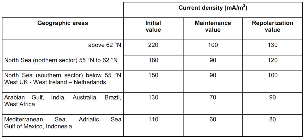
The CivilWeb Cathodic Protection Design Spreadsheet uses default cathodic protection current demand values taken from BS EN 13174. The designer only needs to input the tidal conditions and the aeration of the water. The default values used by the spreadsheet are presented at the bottom of this page. These values are generally thought to be conservative so where better local information is available the spreadsheet allows the user to override the default values.
Cathodic Protection Current Density – General (ic)
This is the cathodic protection current provided per m2 or steel surface area. For anode design this must be calculated for the initial period, maintenance period and final period.
The cathodic protection current densities required are dependent on a number of factors that vary with geographical location, seawater depth and operational depth. The required current density can be measured from a trial polarization of the structure at the installation site or from a trial polarization of a test section at the site. Otherwise conservative estimates based on similar existing structures at similar sites can be used.
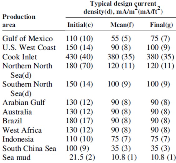
If this is not practical, recommendations for the initial, final and maintenance current densities are provided by national and local standards. Several examples are provided at the bottom of this page for common design situations.
These recommended values are typically quite conservative, usually at least 20% higher than normally encountered. They typically account for harsh weather conditions, waves and sea currents. They do not typically account for the erosive effects of silt or ice on calcareous layers. Where these conditions are likely to exist, a higher value may be justified, particularly for the final cathodic protection current density.
The design current densities are different because of the effects of different water depths, water temperatures, dissolved oxygen content, sea currents, marine growth, salinity, water pH and carbonate content on the properties of the calcareous scale which forms on the outside of protected steel surfaces.
Calcareous Scale
These calcareous deposits reduce the rate of diffusion of oxygen from the water to the steel surface, therefore reducing the required current density to protect the steel. Calcareous scale are minerals precipitated on the steel due to the increased alkalinity caused by the cathodic polarization. They consist of CaCO3, polymorphs, aragonite, calcite, brucite (Mg(OH)2) and the exact composition depends on the water pH, temperature, flow rate and depth.
Dissolved Oxygen
The dissolved oxygen content of the water has a significant impact on the required current density and its effect on required current densities is proportional to the rate at which dissolved oxygen diffuses to the steel surface. Seawater at the surface is saturated with dissolved oxygen from photo synthesis and dissolution from the air. This also varies by geographical area, the dissolved oxygen content at depth in tropical regions will be significantly lower than that in more temperate waters. No allowance is made for areas where the water dissolved oxygen has been depleted, for instance by decomposing organic matter.
Temperature
The effects of the water temperature are complex as the temperature also affects the resistivity, dissolved oxygen content and the formation of calcareous deposits. As the temperature increases the oxygen solubility is lowered but the diffusion constant for oxygen is increased. The net effect is generally a slightly increased required current density for higher temperatures.
Salinity
Salinity mostly affects the seawater resistivity which is used elsewhere in the design calculations. It does also reduce the dissolved oxygen content of the water, reducing the required current densities.
pH
Seawater typically varies between 7.4 and 8.4 pH. Small decreases in pH are sometimes measured near the sea bed due to the decomposition of organic matter. This consumes oxygen reducing the oxygen content in the water and therefore reducing the required current demand. This does however retard the process of calcareous deposits forming on the steel surface.
Marine Fouling
The level of marine fouling expected on the structure largely depends on the location and depth of the structure. Marine fouling generally reduces the area of steel exposed to the seawater and reducing the required current density. There can however be issues where marine organisms on the steel hinder the formation of the protecting calcareous deposits.
Higher current densities are required at the surface due to wave action and marine growth which degrade the calcareous scales. This is reflected in the recommended values given at the bottom of this page.
For steel buried in marine sediments, the current densities required are influenced by temperature, bacterial growth, salinity, hydrogen evolution and the coarseness of the sediments.
Cathodic Protection Current Density – Initial Period (ici)
This is the cathodic protection current density required to achieve cathodic protection of a bare steel surface in a reasonably short period of time. It protects the steel by polarization. The initial current density value includes for some rusting and mill scale which would typically be found on marine steel structures prior to cathodic protection.
The initial current density is always higher than the final current density because the initial current enables the rapid formation of protective calcareous scale on the steel which allows efficient polarization to occur. A higher current density will encourage a thinner and more compact calcareous scale to form which offers better protection. Though if the current density is too high the calcareous deposit will contain more magnesium Mg(OH)2 which offers poorer protection than the calcium carbonate deposits.
The final current density includes for this calcareous scale and some marine fouling to be present which reduce the polarization resistance and therefore the required current demand.
The effects of any coatings must also be included.
Cathodic Protection Current Density – Final Period (icf)
This is the cathodic current density required to repolarize the structure at the end of the cathodic protections design life. This take into account the reduction to the required current demand which takes place due to the calcareous scale and marine fouling which are expected on the structure at this stage. It also takes account of the current density required to repolarize the structure if the calcareous and marine growth layers are damaged, for example if the marine growth is removed during maintenance or a major storm depolarizes the structure.
An appropriate final current density will ensure that the structure is polarized to a potential of between -0.95V to -1.05V throughout the design life of the cathodic protection system. This also minimizes the maintenance current demand.
Cathodic Protection Current Density – Maintenance Period (icm)
This is the mean design cathodic current density expected once the cathodic protection system has attained its steady state protection potential. This protection potential is typically 0.15V-0.20V more negative than the design protective potential. This mean design cathodic current density is typically reduced to around 50% of the initial current density. As the initial current density period is small compared to the overall design life, the maintenance current density can be used to estimate the overall average current density for the system.
Other Considerations
Some special types of structure need to be considered in a different manner to typical marine structures when calculating the required current densities.
For freely flooded compartments and closed compartments with free access to air, design current densities equivalent to 30m-100m depth are recommended. Closed and sealed flooded compartments do not usually require cathodic protection.
For components such as piping which are heated by an internal fluid the design current densities can be increased by 0.001 A/m2 for each 1°C that the steel/environment interface reaches above 25°C. For single wall conduits this can be taken as equal to the expected temperature of the internal fluid.
Different current densities are required for the protection of reinforcing steel in concrete structures. The required cathodic current density is mainly influenced by the reduction of oxygen. Therefore the required current densities are dependent on the atmospheric conditions and the temperature. The required current densities can be adjusted when the ratio (B) of reinforcing steel surface area (m2) to volume of concrete (m3) exceeds 5. In this case the current densities should be adjusted by a factor of 5/B. Some commonly recommended values are given at the bottom of this page.
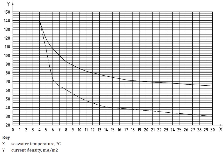
For well coated long distance pipelines geomagnetic or telluric effects should be considered. The potentials can be reduced by installing insulated couplings. Coated pipelines installed on the sea bed tend not to require an evaluation of the initial or final current density. This is because the coating reduces the initial current demand below the maintenance demand and being on the sea bed generally protects the pipeline from being depolarized during storms. For these reasons typically only the maintenance current density is critical. The maintenance current demand is closely dependent on the temperature of the water, particularly where the pipeline is less than 500m deep. A graph is presented at the bottom of this page which can be used to estimate the required maintenance current demands on a pipeline.
For components coated in aluminum or zinc, a current density value of 0.010 A/m2 is recommended for initial, final and maintenance periods. This should be increased by 0.002 A/m2 for each 1°C that the metal/environment interface reaches above 25°C.
Recommended Cathodic Protection Current Densities - General (DNVGL-RP-B401)
Initial and final design current densities (A/m2) for seawater exposed bare metal surfaces;
Mean design maintenance current densities (A/m2) for seawater exposed bare metal surfaces;
Mean design maintenance current densities (A/m2) for protection of reinforcing steel in concrete
Note DNVGL-RP-B401 recommends a value of 0.020 A/m2 is used for initial, final and maintenance design current densities for steel surfaces buried in sediments, regardless of depth or location.
Recommended Cathodic Protection Current Densities – Offshore Steel Structures (BS EN 12495)
Design current densities (mA/m2) for immersed bare metal surfaces;
Note for steel in the extended tidal zone, the above figures should be increased by 20%.
Design current densities (mA/m2) for bare metal surfaces buried in marine sediments;
Recommended Cathodic Protection Current Densities – Harbour Steel Structures (BS EN 13174)
Design current densities (mA/m2) for bare metal surfaces in seawater;
Design current densities (mA/m2) for bare metal surfaces in saline mud;
Recommended Cathodic Protection Current Densities – Other Typical Recorded Values
Recommended Cathodic Protection Current Densities – Pipelines
The two curves presented above are taken from studies of operational non-buried pipelines. The lower curve can be used if there are no significant changes in dissolved oxygen content from the surface to the seabed, no build-up of protective calcareous deposits and low or moderate seabed currents (less than 2 knots). Otherwise the higher curve represents conservative values.
Note that limited data is available for temperatures below 6°C, so a value of 120mA/m2 is recommended in these cases unless better data is available.
Where the temperature of the pipeline is to be above 25°C an adjustment to the above value is required as raised temperatures decrease oxygen solubility and increase the rate of corrosion. An increase of 1mA/m2 is required for each 1°C above 25°C up to a max of 100°C.
For risers or other components in the splash zone, required current densities should be increased by 10mA/m2. Note that splash zones can vary from one geographical location to another, in the North Sea the splash zone can extend to 10m below the surface, in other areas such as the South China Sea this can be as little as 1m.
For pipelines buried either in natural sediments or covered with rock, a design current density of 20mA/m2 should be used regardless of the water temperature, dissolved oxygen content or depth.
Some locations have reported significant deviations from the above curves. A few common examples are shown in the table below.


