Cathodic protection testing is required to verify that the cathodic protection system is active and is performing as designed. This survey should take place within three months of the system being completed for bare steel structures, and within 1 year for coated steel structures. The CivilWeb Cathodic Protection Design Spreadsheet can be used to design the cathodic protection system for any cathodic protective potential. The system should be tested following installation using the methods described below to check that the system is performing as designed.
Cathodic Protection Testing - Potential Survey
The potential survey involves the measurement of the cathodic protection potential of the steel provided by the cathodic protection system. This is fairly straightforward for cathodic protection of harbour structures in seawater and requires only a conventional voltmeter and a portable reference electrode. The negative terminal of the voltmeter is connected to the steel structure above water, and the reference electrode is lowered into the water as close as possible to the structure.
The connection to the steel is a simple metallic connection. The reference electrode is used to make the connection to the seawater electrolyte. Reference electrodes commonly used for field measurements include the Ag/AgCl/seawater reference electrode which has been used as standard for design. Other electrodes may be available and if a different type of reference electrode is used the results will need to be converted before evaluation.
Other types of reference electrode include;
- Saturated copper/copper sulfate reference electrode (CSE). This electrode is more commonly employed for determining the level of protection on onshore pipelines and is not sufficiently stable in seawater for long-term immersion in this environment. It is not recommended for use in seawater.
- High-purity metallic zinc electrode. “High purity” (ASTM B418, type II, or EN 12496, alloy type Z2) or a zinc alloy used for anode manufacturing (US Mil Spec A-18001K or EN 12496, alloy type Z1 or Z3) have a moderately stable potential in seawater and are sometimes used as a reference electrode. However, zinc electrodes are less accurate than silver/silver chloride reference electrodes, and are mostly used in permanent monitoring applications. For permanent installations, a small anodic current should pass through the surface to keep it clean and active.
- Saturated calomel reference electrode (SCE). This electrode comprises mercury and mercurous chloride in a saturated solution of potassium chloride. This electrode is not normally used for site surveys and is more suitable for laboratory applications.
- Saturated silver/silver chloride (Ag/AgCl/saturated KCl). This electrode is similar to the silver/silver chloride/seawater electrode, except that the silver/silver chloride is immersed in a saturated solution of potassium chloride and the potential is not affected by the salinity (or resistivity) of the seawater. As with SCE, the saturated silver/silver chloride electrode is more suitable in laboratory applications.
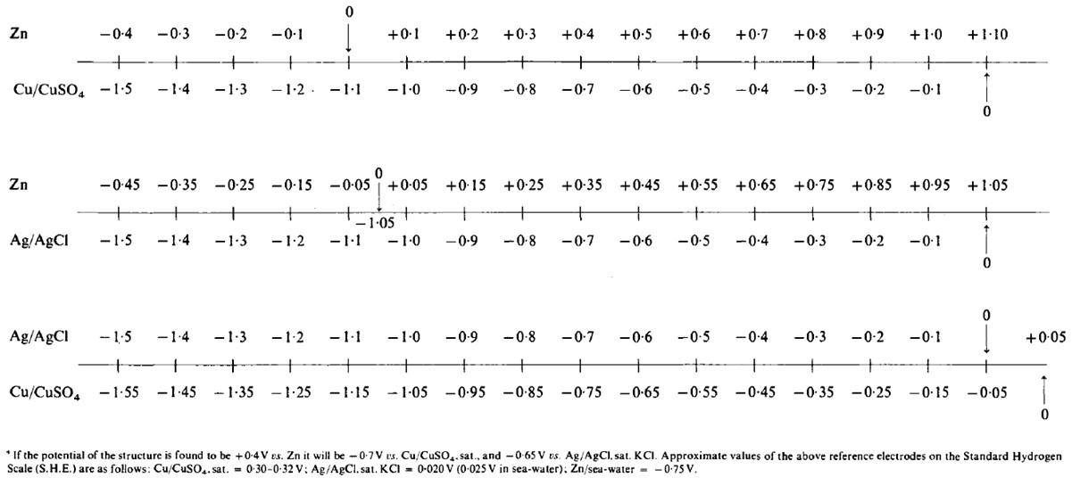
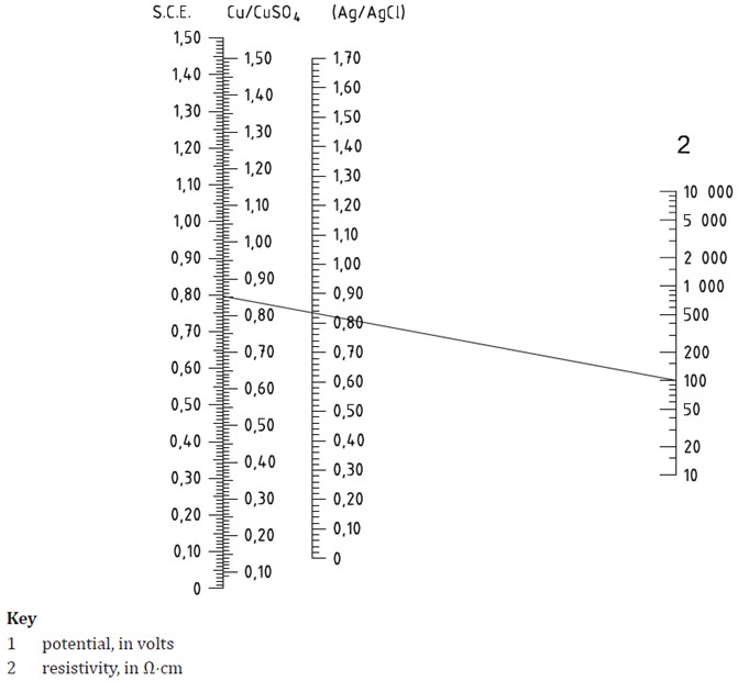
Two simple conversion nomographs are shown below;
The accuracy of the potential measurements can be improved by ensuring that the reference electrode is located as close as possible to the structure, and preventing motion in the water. In some circumstances it may be prudent to employ a diver in the water to ensure the reference electrode is located correctly.
Test instrumentation should be in good condition and should be calibrated as per the manufacturer’s instructions.
Potentials should also be measured at the anodes to ensure that they are performing as per the design. The measured potential at the anode should be more negative than the design closed circuit anode potential. Where more positive readings are measured, this may indicate passivation or excessive current load.
Cathodic Protection Testing - Visual Inspection
A visual inspection should also be undertaken, usually at the same time as the potential survey. The visual survey should include confirmation of the number, type and location of all anodes installed and measurements of the potential at various locations. It should also check the condition of continuity cables and for signs of anode consumption. Any heavy calcareous deposits near to the anodes can indicate overprotection.


