The high mast light pole wind pressure is the effective force which acts on the light pole due to the wind. ILE Technical Report 7 uses BS 6399-2 to determine the wind loading, then includes the following procedure to estimate the effective wind pressure which this causes on the high mast light pole. High mast light poles are not simple flat faced rectangular areas like the sides of buildings so there are a number of additional parameters to consider when determining the effective wind pressures acting on the high mast light pole.
After the effective wind pressures are determined, the overturning moment is used to design the high mast and the high mast light pole foundations. The below methods are used in the CivilWeb High Mast Light Pole Design Spreadsheet in accordance with ILE Technical Report 7.
The Peak Equivalent Static Pressure is the force which multiplies with the wind area to calculate the force acting on the mast. This is calculated using the following equation;
High Mast Reference Pressure (qHE)
The Reference Pressure for high mast light poles is calculated simply from the Effective Wind Speed using the following equation;
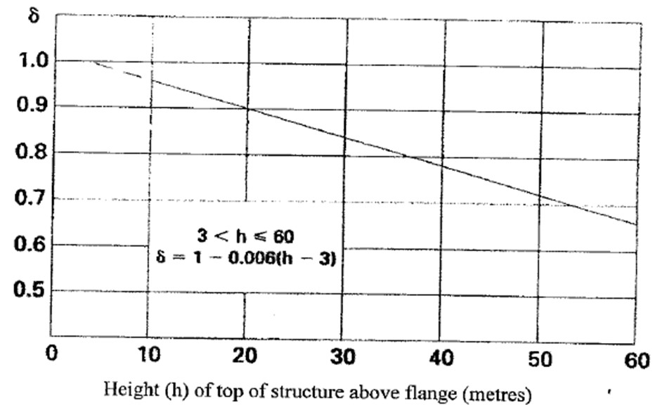
High Mast Size Reduction Factor (δ)
This factor accounts for the high masts small diameter relative to the size of a peak gust. This is calculated as a function of the high mast height and can be derived from the below diagram and equation.
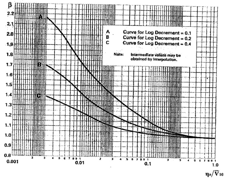
High Mast Response Factor (ß)
The High Mast Response Factor takes account for the way which wind loads are effective on high mast light poles. The Response Factor depends on the Natural Frequency (n0) (Hz) and the damping mechanisms acting on the mast at the hourly mean wind speed at an effective height of 10m (V10).
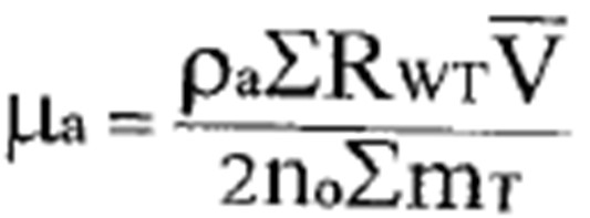
The Log Decrement of Damping can be calculated by adding the Log Decrement of Aerodynamic Damping to the Log Decrement of Structural Damping. These two factors can be calculated using the below equations;
Log Decrement of Aerodynamic Damping
Density of Air (ρa) (kg/m3)
The density of air can generally be taken as 1.22 kg/m3 unless a different value can be justified.
Sum Wind Resistance (RWT) (m2)
This is the product of the Projected Area (A) and the Force Coefficient for the lantern assembly and for the top third of the high mast light pole.
Hourly Mean Wind Speed at top of Mast Height (VT) (m/s)
This is the Site Wind Speed multiplied by the Terrain and Building Factor. This is explained in more detail here.
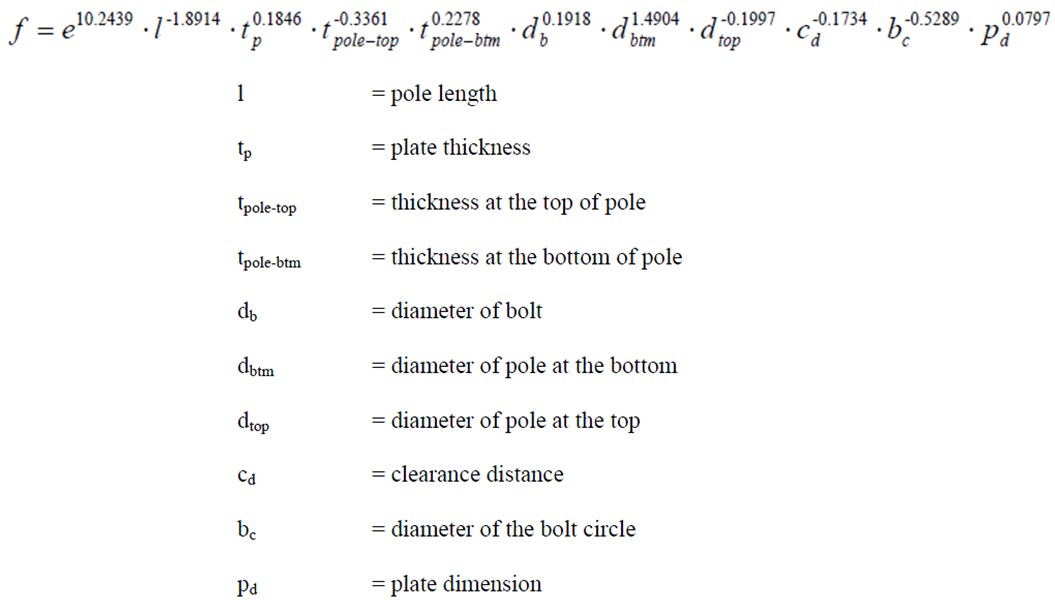
High Mast Natural Frequency (n0) (Hz)
This is the fundamental natural frequency of the high mast and can be given by the manufacturer. Alternatively it can be estimated from the following empirical equation derived from the high mast dimensions;
Log Decrement of Structural Damping
This parameter describes the level of vibration damping which acts on the high mast structure under wind loading. ILE Technical Report 7 recommends that a value of 1.0 is usually appropriate, though it can also be estimated using the below calculations.
Log Decrement of Damping of High Mast Superstructure (Kμ)
This can generally be taken as 0.015 for high mast light poles. This is a conservative value and some high mast light poles may include other energy dissipation elements such as lap joints. If this is the case a more accurate Log Decrement of Damping of High Mast Superstructure can be obtained from testing.
High Mast Light Pole Foundation Influence Factor
This factor allows for the influence of the high mast light pole foundation on the damping of the overall structure. This can be taken from the table below;
The High Mast Response Factor can then be taken from the below graph taken from ILE Technical Report 7.
High Mast Light Pole Force Coefficients (Cf)
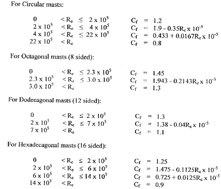
The High Mast Light Pole Force Coefficient takes into account the aerodynamics of the high mast light pole and the luminaires when calculating the wind force. For the mast it is based on a relationship with the high mast poles Reynolds Number (Re).
High Mast Light Poles Reynolds Number (Re)
The masts Reynolds Number is dependent on the high mast light poles Diameter (D), Effective Wind Speed (VH) and the kinematic viscosity of air (v) which can be taken as 1.46x10⁻⁵ m2/s. The high mast light poles Reynolds Number can be calculated using the below equation;
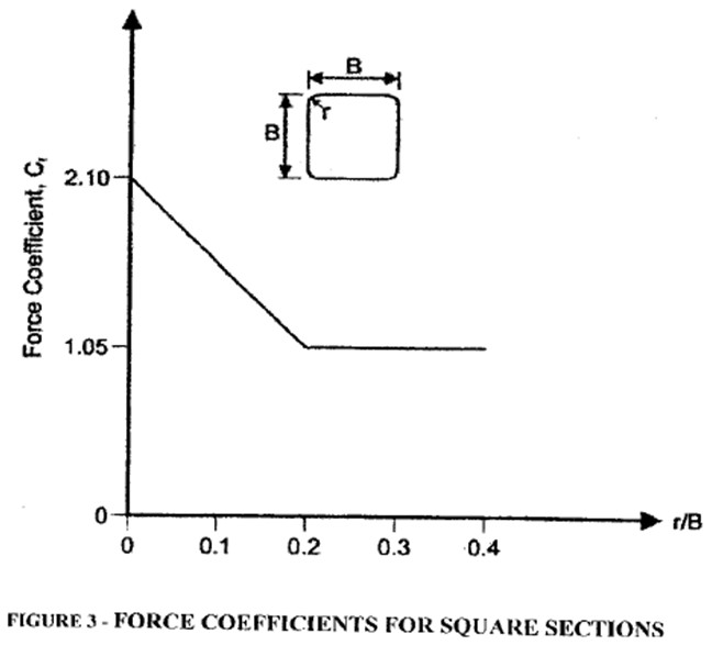
The High Mast Light Pole Force Coefficients for various mast shapes are can then be derived from the below equations. With high mast light poles of other section shapes the Force Coefficients should be obtained from the manufacturer or ascertained from wind tunnel tests.
The High Mast Light Pole Force Coefficients for high mast head frames and luminaires should be obtained from the manufacturer or from wind tunnel tests. The manufacturer will often include this coefficient within the published wind area as an effective wind area or similar.
If this information is not available, the Force Coefficient can generally be taken as 1.0 for luminaires.
High Mast Characteristic Wind Loads
The Characteristic Wind Loading on the high mast light pole can now be determined by multiplying the Peak Equivalent Static Pressures with the Force Coefficient and the Project Area (A). This calculation should then be repeated for the high mast head, luminaires, control boxes and any other projected areas to obtain the total wind loading for the high mast.
Projected Area
This is the area of the component being considered which is exposed to the wind in the direction being considered. So for a circular or regular polygonal section high mast pole, this is the diameter of the pole multiplied by the height of the section being considered.
Wind Resistance
This is the product of the Projected Area (A) and the Force Coefficient for the component being considered.
Wind Load
This is the product of the Wind Resistance and the Peak Equivalent Static Pressure. The sum of the Wind Load on all components is equal to the Horizontal Shear Force acting at the high mast light poles base.
High Mast Light Pole Base Bending Moment
The maximum bending moment which occurs at the base of the high mast light pole can be calculated by multiplying the Wind Load and the Lever Arm for each component considered. The Lever Arm is usually equal to the component height above the base. The summation of all components is equal to the total Bending Moment acting at the high mast base.
Factor of Safety
This characteristic load should then be multiplied by a Factor of Safety. For wind loading this is often taken as 1.25 as recommended in ILE Technical Report 7. This factored loading can then be compared with the Design Moment Capacity of the high mast light pole to check that the design is adequate. If the high mast light pole has greater moment capacity than the moment calculated using the above procedure, then the high mast light pole is adequate. This is the method used by the CivilWeb High Mast Light Pole Design Spreadsheet.
Get your copy of the CivilWeb High Mast Light Pole Design Spreadsheet including full wind pressure calculations now for only £20.
Or why not bundle the CivilWeb High Mast Light Pole Design Spreadsheet with our Street Light Foundation Design Spreadsheet for only £5 extra?
Download Free Trial Version
To try out a fully functional free trail version of this software, please Click Here or enter your email address below to sign up to our newsletter.


