Cathodic protection systems are widely used in the marine industries to protect structures exposed to seawater from corrosion including Accelerated Low Water Corrosion. The CivilWeb Cathodic Protection Design Spreadsheet provides the quickest and easiest way currently available for the design of cathodic protection systems for marine applications.
Introduction to Cathodic Protection Design
When two dissimilar metals are connected in an electrolyte such as seawater, a galvanic cell is produced. The driving voltage in the cell is the difference between the natural potentials of the two metals. Assuming the circuit is closed, this potential difference drives an electrical current. The more negative metal behaves as an anode releasing electrons into the circuit. This causes the anodic material to dissolve more rapidly while the less negative material behaves as a cathode and dissolves less quickly. This is the basis of cathodic protection of metals in water, seawater or soils.
In theory any metal which is more electromagnetic than steel can be used as anodic material to protect the steel in the electrolyte. In practice this is typically aluminium, zinc or magnesium alloys. The electrons release by the anode are consumed in the cathodic reduction of dissolved oxygen on the surface of the steel structure.
Cathodic Protection Design Procedure
The CivilWeb Cathodic Protection Design Spreadsheet completes cathodic protection design in accordance with DNVGL-RP-B401. The design procedure can be time consuming to complete by hand and the iterative optimization process can be difficult. The CivilWeb Cathodic Protection Design Spreadsheet completes the process in seconds with unique optimization tools which show the user the optimum solution for any marine cathodic protection system design.
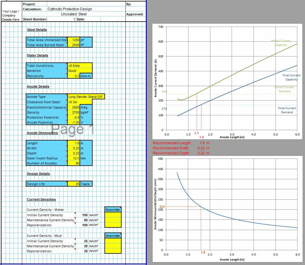
The first step is to calculate how much current demand the structure will require for cathodic protection. This is a function of the surface area of steel to be protected and current density required due to the environmental conditions. The required current density must be calculated for three design conditions, initial polarization, maintenance period and final polarization to achieve the design cathodic protection potential as input by the designer. The CivilWeb Cathodic Protection Design Spreadsheet calculates the required current densities automatically from the guidance in BS EN 13174.
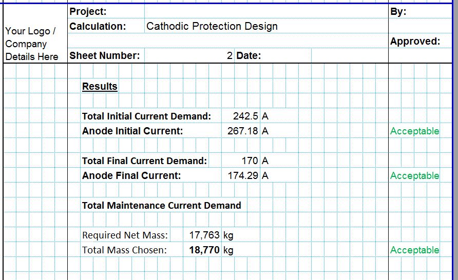
Once the required current demand is determined for all three design checks the anodes can be designed. The current output of the anodes depends on the number, size, shape, type and composition of the anodes. The electrochemical capacity of the anodes is dependent on the material used and the density. The current output of the anodes is also dependant on the resistivity of the seawater. The resistance of the anodes is dependent on the anode type.
The designer can specify any arrangement of anodes and the CivilWeb Cathodic Protection Design Spreadsheet will calculate the current output of the anodes at all three design stages and check whether the arrangement is suitable for the specific cathodic protection system design life.
Cathodic Protection Design Guidance
The CivilWeb Cathodic Protection Design Spreadsheet includes a comprehensive design guide. As well as detailed guidance on the anode design procedure the design guide also includes extensive guidance on;


