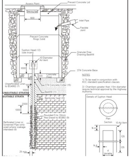
A deep bore soakaway is a special type of rainwater soakaway consisting of a conventional chamber and a narrow bore perforated liner extending to the infiltration medium. These types of soakaway are useful where a very good infiltration medium underlies a deep layer of poor infiltration material, such as gravels underlying a deep layer of clay. In this case the conventional soakaway chamber provides the required storage, while the bored liner extends into the gravel and provides the required infiltration rate. A standard detail is included below.
Deep Bore Soakaway Detail
This type of soakaway can sometimes be used where a conventional soakaway pit, trench soakaway or soakaway crates would be ineffective. Deep bore soakaways are not generally used as garden or driveway soakaways.
Deep Bore Soakaway Construction
The chamber is generally formed using conventional means, typically precast concrete manhole rings. They will not typically include any perforations, unless some infiltration is expecting in the upper soils or if a larger surrounding gravel filled pit is expected to provide some of the required storage capacity.
The chamber will have a concrete base which is penetrated by a steel or plastic liner. This is usually around 100mm or 150mm diameter. Larger diameter liners can be used where there is a limitation to the depth of the liner, for example to avoid contacting groundwater. The liner is inserted into a borehole constructed through the concrete base in the normal manner with a light percussion or rotary auger. Sometimes it is possible to reuse a borehole drilled for site investigation purposes. This saves money on drilling a new hole and removes any uncertainty caused when site investigation information is extrapolated to the soakaway location. This does require the location of the proposed soakaway to be decided at a very early stage of the development.
The diameter of the borehole must be at least 50mm greater than the liner to allow a 25mm thick layer of 10mm or 20mm pea gravel backfill to the annulus between the liner and the surrounding soils. This gravel layer helps to disperse the water evenly as it percolates through the liner into the soil. The gravel layer also allows a bentonite seal to be installed around the non-perforated section of liner.
The liner should only be perforated at the depths where infiltration is expected. A length on non-perforated liner should be included to a depth of around 2.0m below the interface of the infiltration medium. The total length of the liner is dependent on the required infiltration rate, though it may also be restricted by the local groundwater levels. The infiltration rate can be calculated using the larger borehole diameter.
The annulus between the non-perforated liner and the surrounding soils should be sealed with a bentonite seal. This seal prevents the water from being forced up the outside of the liner even when a large head of water is in the storage chamber above the liner. A smaller diameter liner can sometimes be used for the non-perforated sections to allow a thicker bentonite seal to be installed to the annulus.
The liner should protrude around 1.0m into the chamber and should have a syphon hear or similar to prevent any materials from entering the liner which could cause a blockage.
The installation of the borehole through some types of soils can have a smearing effect which can close the horizontal joints leading to a reduced infiltration rate. Where this is suspected, a field test of the installed soakaway can be performed to check that it will perform as designed.
Specification
A typical deep bored soakaway specification taken from the Kent Soakaway Design Guide is included below;
Where the conventional soakaway is to act purely as a storage chamber, it shall be backfilled in accordance with the 600 series clauses of the Department of Transport's "Specification for Highway Works"
In all installations the inspection cover must be sited vertically above the borehole to facilitate future maintenance.
Each location considered for the installation of a soakaway should be investigated by means of a constant or falling head soakage test. These tests should be carried out in the deposits considered suitable and at vertical intervals as agreed with the Engineer. Alternatively a proof test may be undertaken on the installed liner.
When the soakage tests are complete, the borehole could be deepened, if necessary, to provide the required length within the soakage layer and a deep bored soakaway liner installed.
The borehole liner shall have an internal diameter of at least 100mm but normally not more than 250mm. It may be UPVC in accordance with BS 4962 or other durable material agreed with the Engineer. It must be capable of insertion in the borehole without risk of breakage, or damage to the joints.
Perforated slotted or screened pipe shall only be used in that section where soakage is intended. The apertures in such a pipe shall be smaller than any aggregate placed between the liner and the borehole wall. The perforated pipe shall commence a minimum of 2 metres below the interface with the overlying unsuitable strata.
After installation of the lining tube, rounded 5mm to 10mm pea gravel shall be placed in the annulus between the borehole wall and the lining tube to a level 1 metre above the perforated pipe as the casing is withdrawn. Care must be taken to ensure that the level of the aggregate is maintained just above the bottom of the casing to prevent collapse of the borehole. In addition excessive heights of aggregate above the bottom of the casing could jam the casing during withdrawal and risk lifting the liner to the detriment of the installation.
A bentonite seal shall be placed on top of the aggregate to extend nominally 1.0 metres above and below the interface with the overlying unsuitable material. Care should be taken to prevent contamination of the gravel.
As the casing is withdrawn the remaining annulus shall be filled with suitable backfill material or grout as directed by the Engineer.
The removable syphon head shall be in any approved non-rusting material. A suitable design in UPVC is illustrated. It shall have a 10mm diameter air vent at its highest point. It shall be fixed to the liner in a manner agreed by the Engineer. Correctly fitted push fitting syphon heads are acceptable to remove the need for entry into a confined space. .
On completion, if requested, the soakaway shall be tested to the satisfaction of the Engineer.
Where the deep bored liner has to be installed within an existing chamber without a concrete foundation, a Class ST4 concrete floor, 225mm thick, shall be cast to avoid any necessary erosion of the soil at the base of the chamber.
Where the deep bored liner has to be installed within a chamber in which a hole has been made during drilling, or preformed in the base, the annulus remaining after completion of the installation shall be filled with a 225mm thick concrete plug Class ST4.
Where the deep bored liner has to be installed within an existing chamber which does not have a concrete base and which is showing signs of instability then the bottom rings should be underpinned and a concrete floor (Class ST4), 225mm thick be cast beneath them. More serious instability will require additional ground improvement and/or relocation of the soakaway.
All joints, soakaway holes and lifting eyes in the precast concrete rings located in unsuitable strata should be sealed with mortar or other sealing materials approved by the Engineer. This shall prevent seepage of water by any other means than through the deep bored liner.
Where an existing soakaway shows signs of instability it is recommended that after the remedial measures have been completed the bottom two metres of the chamber be sealed with a bituthene coating protected by a 150mm thick dwarf wall formed from Class ST4 concrete. More serious instability may require additional ground improvement and/or relocation of the soakaway.
Related Spreadsheets from CivilWeb;
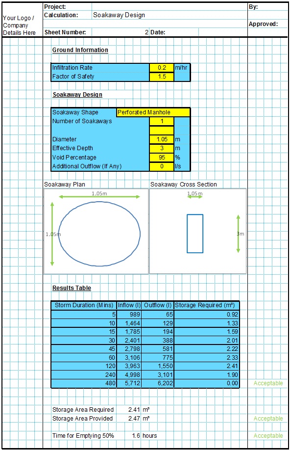
Soakaway Design Spreadsheet
This spreadsheet calculates the requirements for a soakaway system and assists the user to design a suitable system.
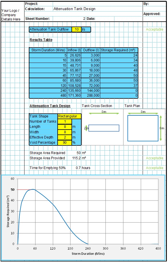
Attenuation Design Spreadsheet
This spreadsheet calculates the requirements for a attenuation system and assists the user to design a suitable system.
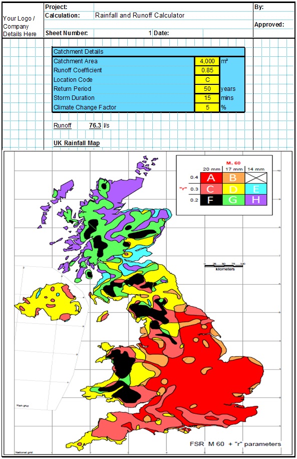
Runoff Calculator Spreadsheet
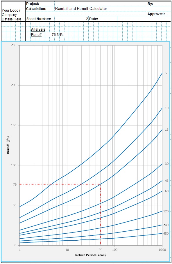
This spreadsheet calculates the design runoff flow for a site in accordance with the a number of different methods including the Wallingford Procedure.
Full Drainage Design Suite
Full drainage design suite (50% Discount) including 7 spreadsheets;
- Colebrook White Pipe Design
- Manning Pipe Design
- Manning Open Channel Design
- Linear Drainage Design
- Runoff Calculator
- Attenuation Design
- Soakaway Design
