The performance of any soakaway system is dependent on the soakaway construction details being designed and installed correctly. This is the case for domestic driveway or garden soakaways and larger commercial systems. This page includes describes some important construction details for soakaway pits, soakaway trenches and soakaway crate systems.
Soakaway Base Gradient
It is important that the base of a soakaway is constructed on a level gradient. This ensures that there is uniform ponding and infiltration across the base of the soakaway. The base should be constructed flat to a tolerance of 10mm in 3m.
If the base is constructed on a gradient the water will naturally collect at the low points. This encourages sediment to collect at these locations which can lead to them becoming blocked. This in turn can lead to some water becoming trapped at the low points reducing the storage capacity of the soakaway and introducing issues with stagnant water. This is a particularly important consideration for infiltration trenches, but can still be an issue for soakaways.
Concrete Base
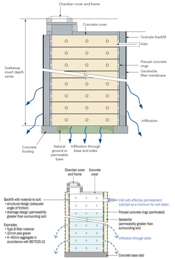
A concrete base must be installed where precast concrete soakaway units are used. This is to provide a suitable level base to install the units and to prevent the underlying soils from being washed out or destabilised by the infiltrating water.
In some cases the centre of the base can be left open to allow infiltration through the base. This is often ignored as the infiltration volume through a small diameter soakaway is usually small and a solid concrete base is easier to construct. Designs undertaken in accordance with BRE 365 ignore infiltration through the base anyway as it is likely to become blocked with sediments.
It is also easier to remove accumulated sediments when a concrete base is present. This also removes the possibility of the units being accidentally undermined during the sediment removal process.
Inspection Chambers
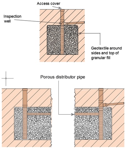
All soakaways should include an inspection chamber which will allow the location of the soakaway to be seen, the water quality to be measured and for the inflow point to be inspected. The inspection chamber should extend to a footplate at the bottom of the soakaway and should be perforated so that the water level in the soakaway can be measured. Where a precast concrete storage chamber is installed this will serve as the inspection chamber. Where the soakaway does not include an open storage chamber a 225mm perforated pipe extending from the surface to the bottom of the soakaway should be provided.
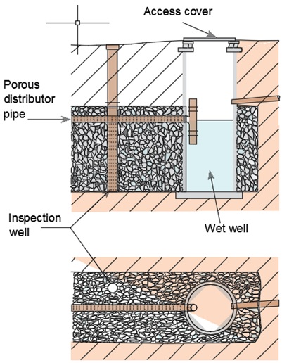
Infiltration trenches should have at least two inspection chambers, one at each end of the trench. Long or non-straight infiltration trenches may require more than two inspection chambers. A larger manhole style inspection chamber is usually included at the inflow point. Where multiple inflow points are used an inspection chamber should be included for each inflow.
Typical Soakaway Details
This section includes a number of typical details given in the literature.
Soakaway Pit Details
Trench Soakaway Details
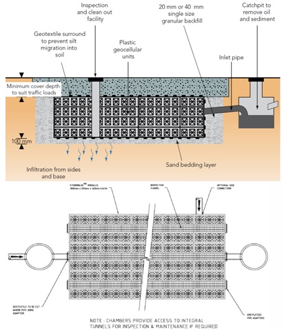
Soakaway Crate Details
Related Spreadsheets from CivilWeb;
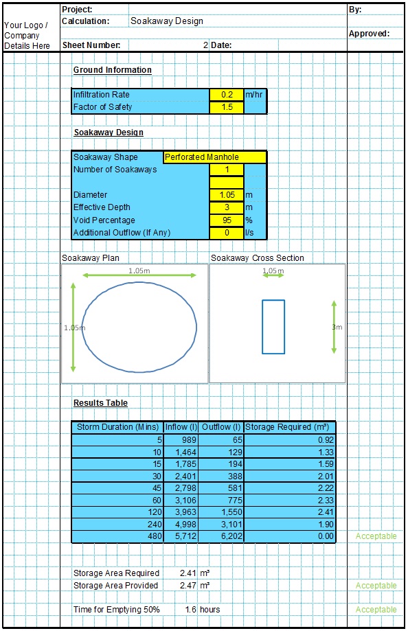
Soakaway Design Spreadsheet
This spreadsheet calculates the requirements for a soakaway system and assists the user to design a suitable system.
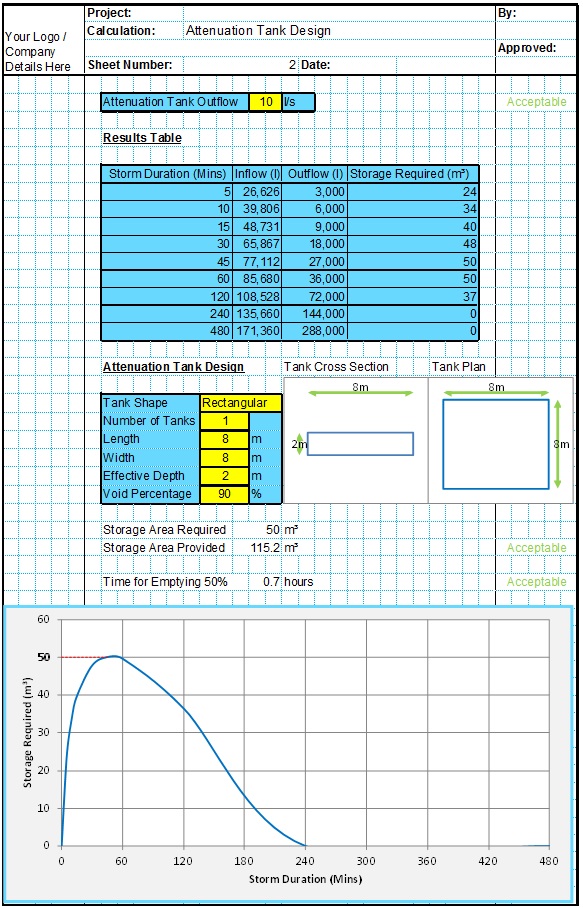
Attenuation Design Spreadsheet
This spreadsheet calculates the requirements for a attenuation system and assists the user to design a suitable system.
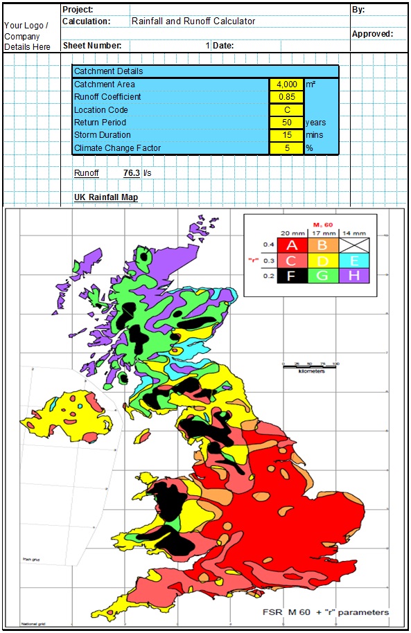
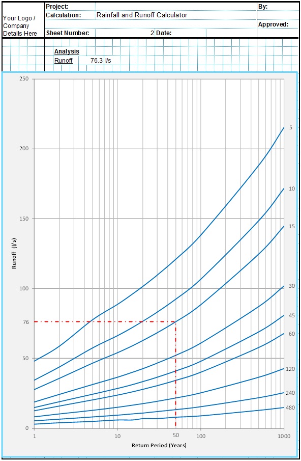
Runoff Calculator Spreadsheet
This spreadsheet calculates the design runoff flow for a site in accordance with the a number of different methods including the Wallingford Procedure.
Full Drainage Design Suite
Full drainage design suite (50% Discount) including 7 spreadsheets;
- Colebrook White Pipe Design
- Manning Pipe Design
- Manning Open Channel Design
- Linear Drainage Design
- Runoff Calculator
- Attenuation Design
- Soakaway Design
