Pipeline protection slab design is often neglected in favour of standard details and generic slab designs. This is usually a mistake as pre-cast utility and pipe protection slabs and standard design details are often very lightly reinforced and not designed o take significant imposed loadings, particularly where the slab needs to span over a wide trench. The CivilWeb Concrete Protection Slab Design Spreadsheet automates much of the detailed design process guaranteeing a suitable and fully compliant design can be completed in seconds.
Pipeline protection slabs are standard design details which are used to protect pipelines and other underground services from imposed loads on the surface. They are usually required when there is a requirement to install the pipeline at a shallow depth, though sometimes concrete protection slabs are used to protect deeper pipelines from heavy imposed surface loads.
Drainage pipes, pipelines and service ducts are usually protected from imposed loads on the surface by their depth. The imposed loads at the surface are dispersed in the soil beneath. This means that the effective load on a pipe beneath the ground diminishes quite quickly as the pipe gets further from the surface. A depth of around 1.2m is sufficient to protect most pipelines from general surface loads such as normal highway traffic.
Underground pipes resist both imposed loads acting on the surface above the pipe and also load from the deadweight of the soil on top of the pipe. The way the pipe resists these forces depends on the type of pipe. Rigid pipes such as concrete pipes or clay pipes are much stiffer than the surrounding soils. They resist imposed loads through the strength of their material and transfer the loads into the soils beneath them. Flexible pipes such as plastic pipes and steel pipes are not much stiffer than the surrounding materials so they deform under imposed loads. This deformation however mobilizes the strength of the soils to either side of the pipe which acts to resist the imposed loads.
Correct pipeline protection slab design ensures that the slab effectively spans over the pipeline installation trench and transfers the imposed loads to the surrounding soils on either side of the pipe. As well as correct pipeline protection slab design, the correct pipe protection slab details must also be included in the design. These include ensuring that the slab spans the pipe installation trench properly and that a layer of compressible material is included beneath the pipeline protection slab to ensure that the deflection of the pipe protection slab under load does not simply transfer load into the pipe instead of transferring it to the surrounding soils.
Pipeline Minimum Cover Depths
Most standard types of pipeline have a minimum cover depth which they must achieve based on standard surface loadings. One source for drainage pipes is Sewers for Adoption which recommends the minimum cover depths summarized below. Other standards will vary so any applicable standards should be checked before detailed pipeline design but the Sewers for Adoption values are generally typical.
- 350mm – beneath gardens, paths and other areas where vehicular traffic is impossible
- 500mm – beneath domestic driveways, parking areas and yards where access to vehicles over 7.5T is impossible. Height restriction goal posts may be used to restrict access to large vehicles.
- 900mm – beneath similar areas where limited access to heavy vehicles is allowed, such as domestic areas with occasional refuse truck or delivery wagon access.
- 900mm – beneath agricultural land or public spaces
- 1,200mm – beneath highways and other areas with unrestricted access to heavy vehicles (>7.5T)
Where these criteria can be met no further structural design calculations are required except in cases of exceptional or unusual imposed loadings (at a port or airport for example), where construction traffic will operate over the pipe before the full cover depth is in place or where the pipe will be very deep and large loadings from the soils are expected. A preliminary check can be undertaken using standard pipe design tables such as those in BS 9295.
Pipeline Protection Slab Design
In most cases it is advisable that the above criteria are met wherever possible. However in some cases it may not be practical to install pipes at the required depth. This may be due to clashes with other services, ground conditions or hydraulic considerations. In these cases one of the following options should be chosen;
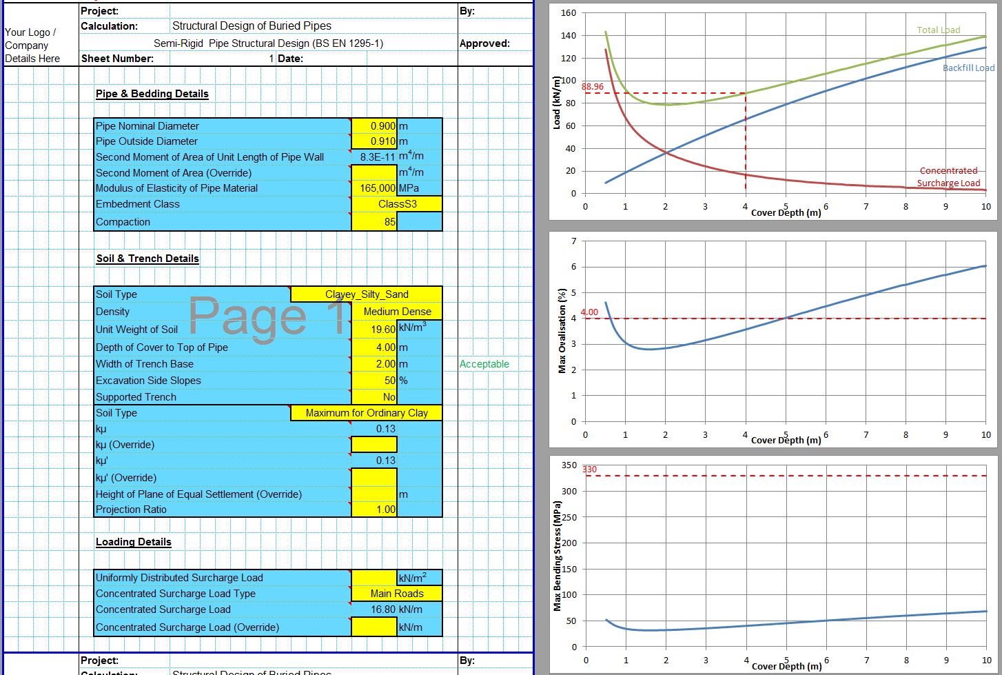
- The pipe could be proven to be structurally adequate for the expected imposed loads through calculation. The structural design of drainage pipes can be undertaken by hand or with specialist software such as the CivilWeb Buried Pipe Design Spreadsheet.
- The pipe could be installed with an upgraded bedding or concrete surround. This will increase the load bearing capacity of the pipe. This can also be analysed using the CivilWeb Buried Pipe Design Spreadsheet.
- Install a stronger pipe. This could be a stronger concrete pipe than standard or a switch between materials such as installing a ductile iron pipe.
- The pipe could be installed with a concrete protection slab.
Pipeline protection slabs are often used where minimum cover depths are not achieved because they are a relatively straightforward and standard method. It is often not worth employing a designer to review the design, particularly for short runs of small diameter pipes. Switching pipe types or materials is expensive and can be difficult to detail.
Although pipe protection slabs are common they are often simply installed in accordance with a standard detail, rather than detailed calculations being undertaken. It is very common for totally unsuitably thin utility and pipe protection slabs to be installed over shallow pipes which will take substantial loads.
Pipeline Protection Slab Design Spreadsheet
Utility and pipe protection slabs can be designed as a simple concrete beam spanning over the width of the trench. In order to complete the required calculations the CivilWeb Concrete Protection Slab Design Spreadsheet completes the following steps;
- The designer input surface loads are adjusted to account for the cover depth above the pipe protection slab. The spreadsheet uses a Boussinesq analysis to calculate the dispersion of the loads and calculate the effective point loads and universally distributed loads acting on the surface of the concrete protection slab. A detailed explanation of these calculations is included in our loads on buried pipes post which includes Boussinesq analysis of loads on underground structures.
- The adjusted loadings from the Boussinesq analysis are then input into a beam analysis module which calculates the maximum bending moments and shear forces acting on the slab.
- These maximum bending moments and shear forces are used to complete the detailed design of the slab and its reinforcement.
This procedure can be time consuming to complete by hand, particularly the Boussinesq analysis and the beam analysis. The CivilWeb Concrete Protection Slab Design Spreadsheet completes these calculations instantly for any depth of pipe or loading conditions. Our unique reinforcement design tools allow the designer to quickly optimize the slab thickness and reinforcement requirements.
Get your copy of the CivilWeb Concrete Protection Slab Design spreadsheet now for only £20.
Or why not bundle with the CivilWeb Buried Pipe Design spreadsheet for only £5 extra?
Or save £50 by buying our full Drainage Design Suite including all our drainage design spreadsheets.
Download Free Trial Version
To try out a fully functional free trial version of this software, please Click Here or enter your email address below to sign up to our newsletter.
