A fin drain is a common general name given to prefabricated french drain units consisting of a three dimensional planar geosynthetic composite material with a carrier pipe at the bottom. The geosynthetic composite material is installed vertically with the bottom installed in a special slot in the carrier pipe. Generally the carrier pipe used with fin drains is not perforated.
The filter fabric allows water to enter the system but prevents fine sediments from entering and potentially clogging the geosynthetic materials or the carrier pipe. The geosynthetic composite material allows water to travel vertically at a very high rate of permeability. The water then enters the carrier pipe through slots at the top which then conveys the water to a suitable outfall.
This arrangement has a very high permeability in the in-plane direction which allows the fin drain to transfer runoff water very efficiently through to the carrier pipe. This allows the findrain to be installed in a much narrower trench than a traditional french drain with the same runoff capacity.
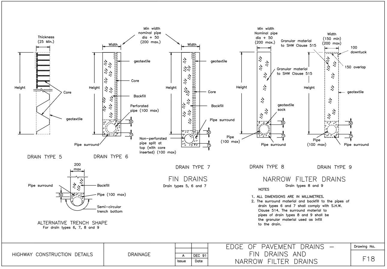
Some typical fin drain details are included below taken from the Highways Agency.
Typical Uses of Fin Drains
Fin drains are usually used as edge drains installed alongside highways and are typically installed using automated fin drain laying machines. They are also commonly used for golf courses and sports fields where a wide french drain trench would be disruptive.
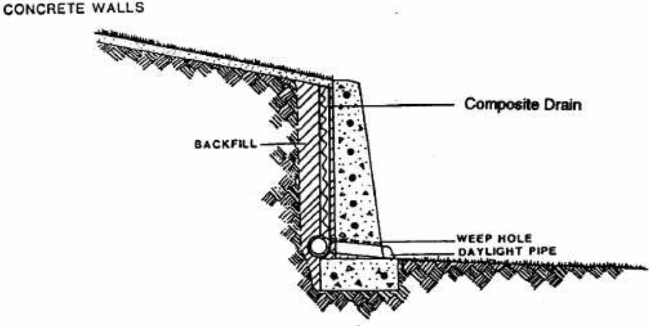
Findrains can also be installed behind retaining walls of all kinds to prevent water from collecting behind the retaining wall. In this case weep holes can be installed through the retaining wall where an outlet is not available behind the retaining wall. An example of this detail is included below. Fin drains are also sometimes known as geocomposite drains, vertical drains or strip drains.
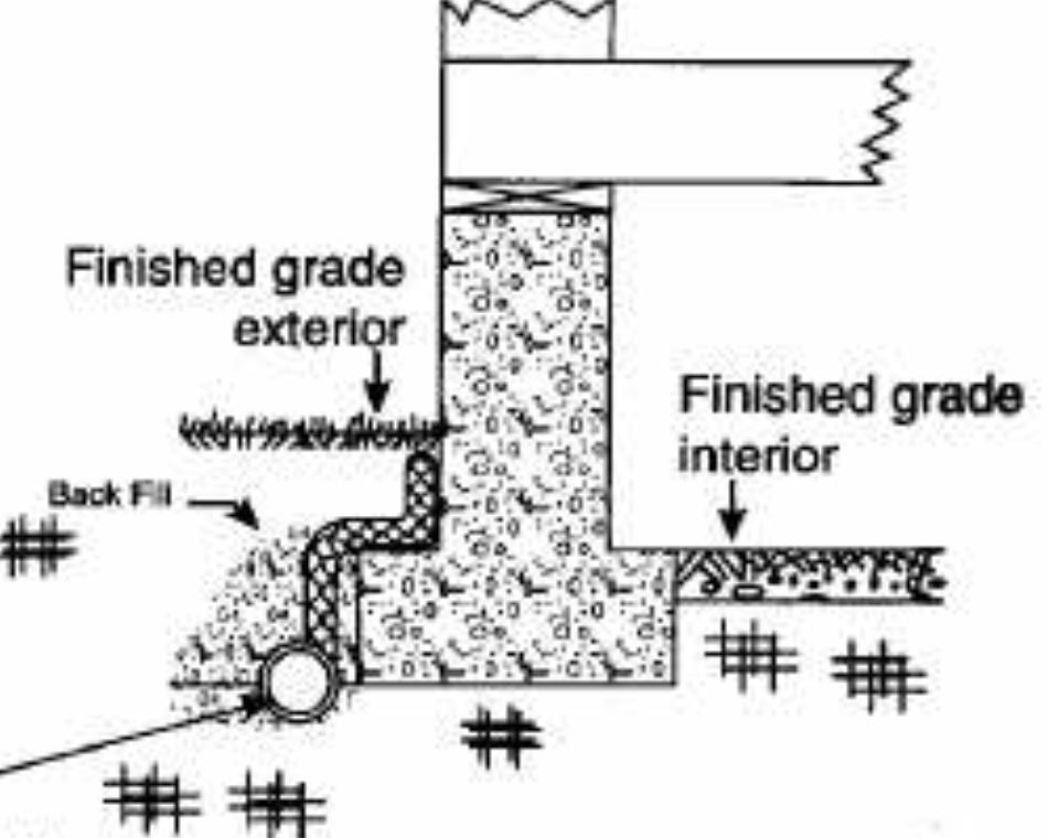
Fin drains are also commonly used to prevent ground water or surface water runoff flow through foundations, particularly where water ingress into a basement needs to be prevented. An example of a findrain used for this purpose is included below.
Findrains are often used as interception drains or curtain drains for spring water or to intercept groundwater. The vertical nature of the fin drain acts as an impenetrable barrier to groundwater. Any groundwater encountering the fin drain will quickly fall through the geocomposite material and into the carrier pipe below. This is often used where natural springs or groundwater movements need to be prevented. Note that where water will only enter the fin drain from one side, the permeability of the fin drain may need to be adjusted to suit water entering on one side only.
Fin Drains or Narrow Filter Drains?
Where there is a requirement for the french drain to be installed in a very narrow trench, fin drains are often the best option. Narrow filter drains can be used in some cases. As narrow filter drains are just narrow versions of traditional french drains, often the trench width is not sufficient to handle the required runoff volume. In these cases a fin drain can offer significantly better runoff capacities.
Fin drains are typically designed using the simple flow rate information provided by the manufacturer so the design process is very simple. Narrow filter drains can be designed using a design spreadsheet such as the CivilWeb French Drain Design spreadsheet. A spreadsheet allows the designer to quickly optimise the french drain width. This results in narrower french drain trenches than typical hand calculations.
Fin Drain Filter Fabric
The geosynthetic composite includes a geotextile french drain filter fabric which prevents fine sediments from the surrounding soils from entering the system and potentially clogging the pipe or reducing its hydraulic capacity. This geotextile filter fabric is often glued or sewn to the geocomposite material.
The findrain filter fabric must comply with many of the same performance and durability requirements as traditional french drain filter fabrics. Highways Agency guidelines include the following requirements specifically for fin drain filter fabrics;
- The fin drain filter fabric should have a tensile strength of at least 5.0kN/m at break in both directions.
- The fin drain filter fabric should have a minimum failure strain of at least 10% determined as per BS EN ISO 10319.
- The fin drain filter fabric should have a minimum puncture resistance of 1,200N determined as per BS EN ISO 12236.
- The fin drain filter fabric should have a minimum tear resistance of 200N determined as per ASTM Standard D4533-91 (1996).
- The fin drain filter fabric should have a size distribution of pore openings such that the apparent opening size O90 determined as per BS 6906-2 is in accordance with the specification.
- The fin drain filter fabric should have a guaranteed permeability rate stated by the manufacturer. This should be for flow in either direction, normal to its principle plane. The published rate should be achieved under a constant head of water of 100mm with a maximum breakthrough head of 50mm as determined in accordance with BS 6906-3.
- The fin drain as a whole should be able to handle a flow rate at least 75% of the published flow rate on the side or sides where inflow occurs. This should be checked with direct measurement of the inflow rate as per BS 6906-3.
Fin Drain Details
It is important that fin drains are correctly detailed and installed in accordance with the specification in order to ensure that they achieve the expected performance.
- Fin drains are capable of being jointed either longitudinally or laterally into carrier pipe systems and access chambers. Each findrain unit should be self-jointing in order to create a single continuous length of fin drain. These joints should be formed in such a way as to prevent ingress of fine sediments into the fin drain through the joints. For fin drain joints running parallel to the direction of flow this can be achieved with lengths of geotextile filter fabric with a minimum overlap of 150mm. Fin drain joints should have inflow rates comparable to those outlined above.
- Carrier pipes used in fin drain systems can be either perforated or porous. Fin drain carrier pipes should have a minimum ultimate pipe stiffness (STES) value of 1.4kN/m2. Fin drain carrier pipe joints should be installed in a similar manner to conventional perforated pipes. Perforated pipe design for fin drains is undertaken in the same manner as for traditional french drains.
- The backfill material used for fin drains is usually the arisings from the trench excavated to install the drain. This material will generally have the same permeability as the surrounding soils and therefore will not affect the performance of the fin drain. For this reason imported filter backfill material is not generally required for fin drains, which reduces the cost.
- The gradient of the fin drain will depend on the size of the carrier pipe and the volume of water to be conveyed. In this way the design of fin drains resembles that of traditional french drains. See our post on French Drain Grade for further info.
Fin Drain Installation
Fin drains should be installed in accordance with the specific manufacturer’s instructions. Findrains assembled onsite should be stored and assembled in a clean and dry area of the site. Care should be taken to prevent wind borne dust and particles from settling on the fin drains geotextile filter fabric as this can reduce the performance of the fin drain. Any findrain components which have been contaminated will need to be replaced.
Fin drain geotextile filter fabrics are often sensitive to ultraviolet light, for example from direct sunlight. Generally these filter fabric materials should not be stored in an area subject to daylight or any other source of ultraviolet light for more than around 50 cumulative hours. Any materials which are exposed to ultraviolet light in excess of 50 hours should be replaced.
The bottom of the trench needs to be free of irregularities and either hard or soft spots which could damage the fin drain units. Hard or soft spots should be removed and any cavities filled with suitable material before the fin drain units are installed in the trench.
One side of the fin drain is typically installed hard up against one of the trench walls. This face of the trench needs to be sufficiently clean, vertical and free of protrusions such as tree roots or rocks. This will enable the face of the fin drain to be installed suitably closely with the face of the trench wall.
Many of the typical considerations for installing fin drains are similar to those for traditional french drains such as digging the trench and not compacting any surrounding soils. See our post on French Drain Installation for further details.
Similar to conventional french drains and other SUDS, fin drains need to be protected from any large construction loads. The findrain needs to be protected from silty site runoffs which are common on construction sites. Similar sediment interception measures can be taken as those to protect french drains.
Fin Drain Maintenance
Fin drains do not typically require any maintenance during their design life other than occasional clearing of any sediments from the fin drain carrier pipe. Care should be taken during the design process to minimise any sediments able to reach the fin drain. A filter strip is usually a convenient and cost effective solution to runoff quality problems. See our French Drain Clogged post for further details of maintenance issues for french drains and fin drains.
Get your copy of the CivilWeb French Drain Design spreadsheet now for only £20.
Or why not bundle with the CivilWeb Soakaway Design spreadsheet for only £5 extra?
Or save £50 by buying our full Drainage Design Suite including all our drainage design spreadsheets.
Download Free Trial Version
To try out a fully functional free trial version of this software, please Click Here or enter your email address below to sign up to our newsletter.
