The long term performance of a soakaway is dependent on the level of clogging which occurs to the surrounding soils. This clogging is caused by small sediment particles which enter the soakaway with the runoff and block the pores of the surrounding soils. This clogging reduces the effective infiltration rate of the soils and over time can cause the soakaway to fail. The lowered infiltration rate can also cause the soakaway to retain some stored water during periods of heavy rain which can lead to microbial growth, further reducing the infiltration rate.
The rate at which this clogging occurs and the effect that it has on the infiltration rate achieved is dependent on characteristics of both the surrounding soils and of the sediments. In some cases the surrounding soils such as some clays have a similar infiltration rate to the accumulated sediments. In this case the effect of the clogging is minimal. Therefore for sites with low infiltration rates, pre-treatment for sediment removal may not be a major concern. Accumulated sediments will have a similar infiltration rate to silty soils, around 1x10^-6 m/s. Any soakaways designed with similar infiltration rates will not be negatively impacted by the accumulated sediments.
Sediment Interception Methods
One way to prolong the life and reduce the maintenance costs of a soakaway is to provide some manner of pre-treatment to remove some of the sediments from the runoff before it enters the soakaway. There are many different methods available and some can be used in combination with others to provide a huge number of options. Some of these methods are detailed in this section.
Specifying the correct pre-treatment method can be affected by the following factors;
- Space – Some underground systems can take very little space, particularly source control devices where inlets would be required anyway. Typically the lower the space requirement, the poorer the treatment performance and higher the capital and maintenance costs.
- Access – Most methods will require some form of maintenance which will require access for plant and equipment. This can be overlooked where limited space encourages the designer to specify a small below ground method without considering the associated above ground maintenance access requirements.
- Types of contaminants to be removed – For soakaways this is usually small sediments which will clog the soakaway and oils which should not be discharged into the ground. Specific sites particularly industrial sites will often include contaminants specific to the site use which may need careful consideration. All interception methods have different performances for different contaminant types so care must be exercised by the designer.
- Type of inflow – Where inflow is through sheet flow into linear inlets, a filter strip or treatment channel may be appropriate. For concentrated inflows a swale or similar conveyance method may be appropriate. Otherwise a system of separators, filtration devices or catchpits may be appropriate.
- Type of storm events – It may not be practical to specify an interception method which can accommodate full treatment of the design storm runoff. In many cases it can be acceptable to include bypass devices or flow control devices to ensure that adequate treatment is achieved for all storm events. This can include a lower level of treatment in storm conditions, though this will depend on the type of runoff, the expected contaminants and the water quality requirements.
- Whole life costs – The capital costs of different methods can vary massively and is dependent on the specific requirements of each site. Maintenance costs must be included in any evaluation and the reduced maintenance requirements of the soakaway or any other connected devices should be included.
Source Controls
Simple source control methods such as ensuring that paved surfaces are regularly swept and roofs are regularly cleaned can have a big impact on the level of sediments entering the soakaway system. The costs of such measures can be offset against the cost of maintaining the soakaway and any other sediment interception methods employed.
Filter Strips
A filter strip is a strip of land where sediments and other contaminants are removed by vegetation as the runoff flows over the ground as sheet flow. These are very useful where the runoff enters the drainage system as sheet flow into an inlet such as a filter drain, swale, or straight into an infiltration trench.
Swales
These act in a similar manner to a filter strip described above. The swale must be suitably designed to treat flows at low velocities. Suitable vegetation must also be provided and maintained within the swale.
Detention or Sedimentation Basin
Runoff is allowed to enter a large basin where it is detained for long enough for the sediments to settle. Then it is allowed to outflow to a soakaway.
Catchpits or Sedimentation Manholes
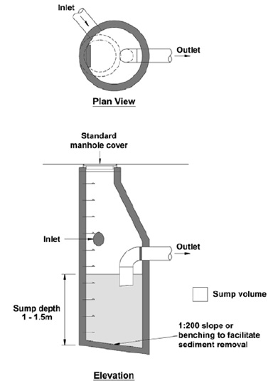
A catchpit is similar to a typical manhole chamber except there is a permanent pool of water at the base. This reduces the velocity of the water to allow some sediments to settle at the base of the pool where they are stored. The sediments are then removed as part of a regular maintenance procedure. They can also be designed to store some floating contaminants and debris. A typical detail taken from the SUDS Manual is shown on the next page.
The catchpit should be designed to accommodate the design storm event and should limit flow velocities to less than 0.3m/s to encourage settlement of sediments.
A catchpit will not remove dissolved or emulsified contaminants. Relatively small sediments will also pass through the device and there is a high risk of sediments becoming re-suspended during high flow events. This makes catchpits of limited use for protecting soakaways as the sediments which clog up surrounding soils are often very small (<6 μm).
Due to the above limitations catchpits are usually seen as a cheap and simple solution where large sediments are expected in the runoff or as a pre-treatment to a more sophisticated treatment method downstream.
Inlet Devices
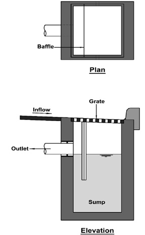
Various devices are available which can be inserted into standards inlets to encourage the settlement of sediments. These can take the form of sump and baffle configurations or as filtration inserts. A typical sump and baffle arrangement is shown below.
Typical inlet arrangements can be ineffective and are not usually used as a sole means of treatment. They usually have a limited capacity for storing sediments and therefore require frequent maintenance. Sediments are also susceptible to re-suspension during high flow events. They can however be useful as the source control part of a larger treatment process including more sophisticated methods downstream.
Treatment Channels
There are some linear drainage channels which include either separation of filtration devices to remove sediments from the runoff at the inlet.
The separation type treatment channels use a series of weir and baffle plates to encourage the settlement of sediments and trapping of lighter than water contaminants such as oils and fuels. They will not remove any dissolved contaminants. Some bioremediation can take place through the wetting and drying cycles of the sediments stored in the device.
The filtration type treatment channels use a filter medium to remove sediments, oils and some dissolved contaminants. Again some bioremediation can take place through the wetting and drying cycles of the filter medium.
These systems include some limitations;
- Often they can only effectively treat small volumes of runoff, between up to 25m² per linear metre for separation channels and up to 100m² per linear metre for filtration channels.
- They require regular maintenance to remove stored sediments and oils. The maintenance requirement needs careful planning as in some cases the need for maintenance may not be apparent from the surface.
Hydrodynamic or Vortex Separators
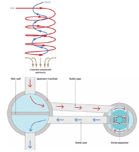
Hydrodynamic or Vortex Separators work by forcing the water through a helical path through the device, as illustrated in the below diagram taken from the SUDS Manual.
The centrifugal path of the water extends the residence time within the unit, encouraging sediments to settle. The centrifugal forces created by the helical path of the water also forces sediments to move towards the centre where the water velocities are lower. This again encourages settling of the sediments.
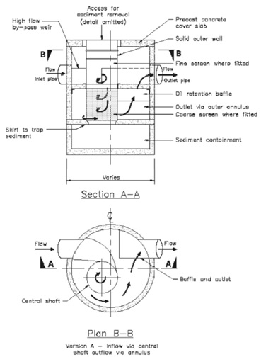
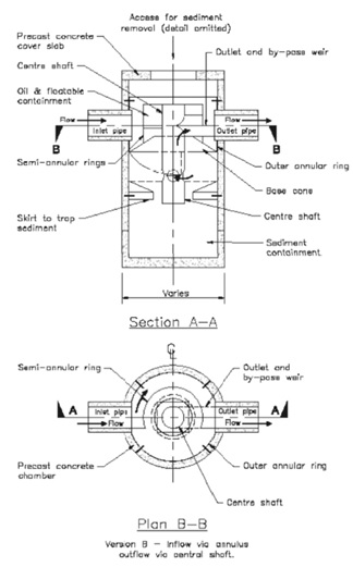
Two main configurations of vortex separator are available, here referred to as version A and B.
- Version A – Inflow is introduced tangentially into the central core of the chamber. It is then directed down a central core in a helical motion. Sometimes a screen is fitted to the central core to trap large sediments. The sediments remain in constant motion in the central core which prevents clogging of the screen. The water then is allowed to outlet through the outer chamber annulus again through a helical path.
- Version B – Inflow is introduced tangentially into the outer annulus of the chamber. This forces the water into a helical path through the chamber which increases the residence time and encourages the sediments to settle. The water then flows up through a central core, again in a helical path to the outlet.
These are illustrated in the below diagram taken from the DMRB;
The design of these units means that a relatively large amount of sediments can be removed in a small space, so they are often used where space limits the application of other methods. They can also be designed in conjunction with a bypass device which allows large flows to bypass the unit. In these cases the units need not be able to handle the full volume of runoff from the design storm.
There are two main types of vortex separators;
- Simple vortex separators which rely on a rotating flow field which is induced in the device to extend the flow path and residence time.
- Advanced vortex separators include internal components to enhance the separation process and prevent re-suspension of settled sediments.
These systems include some limitations;
- They do not remove smaller sediment particles (<115 μm) or dissolved or emulsified contaminants. As the sediments which typically clog up infiltrating soils around a soakaway are very small (<6 μm), this limits the usefulness of vortex separators for use with soakaways. The removal of small sediments can be adjusted by reducing the flow rate through the device. A smaller flow rate leads to longer residence time within the device, leading to smaller particles being settled out and removed. This can mean that during high volume events if the flow rate increases, the performance of the unit removing sediments will deteriorate. Often flow control devices are used in conjunction with vortex separators.
- They require regular maintenance including removal of stored sediments and oils. If this is not done sediments are likely to be re-suspended and discharged during high flow events. Anaerobic conditions can also be created within the device. Alarms can be fitted to alert users that they need to be emptied.
Filtration Systems
Filtration systems work by forcing the runoff through a filtration medium which traps sediments and other contaminants. They can be configured to trap very small sediment particles and even dissolved contaminants. They can also be designed to include some chemical processes to remove even more contaminants.
The filter medium is usually contained in a cartridge which can be replaced when required. Many different types of filtration medium are available including leaf compost, fabrics, cellulose, activated charcoal, perlite and zeolite. Each has different filtration properties and performances and can be tailored to the particular contaminants expected on each site.
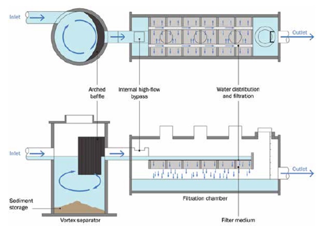
As the filter cartridge will need to be replaced when it becomes blocked, filtration devices are often combined with other sediment removal processes such as vortex separators to remove the large sediments before they enter the filtration device. This will reduce the frequency and costs of maintenance of the filtration device. This arrangement is illustrated in the diagram on the next page taken from the SUDS Manual.
These systems include some limitations;
- They require regular maintenance and replacement of filter cartridges can be expensive, particularly where no pre-treatment is included. It can be difficult to know when the cartridge needs to be replaced so a regular maintenance schedule must be in place.
- There can be issues with purchasing replacement filter cartridges if the manufacturer ceases trading or manufacturing the type required.
Many filters require the flow to pass vertically through the filter medium which can affect the invert levels of inlets and outlets.
Related Spreadsheets from CivilWeb;
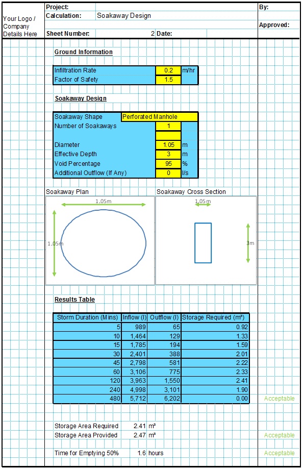
Soakaway Design Spreadsheet
This spreadsheet calculates the requirements for a soakaway system and assists the user to design a suitable system.
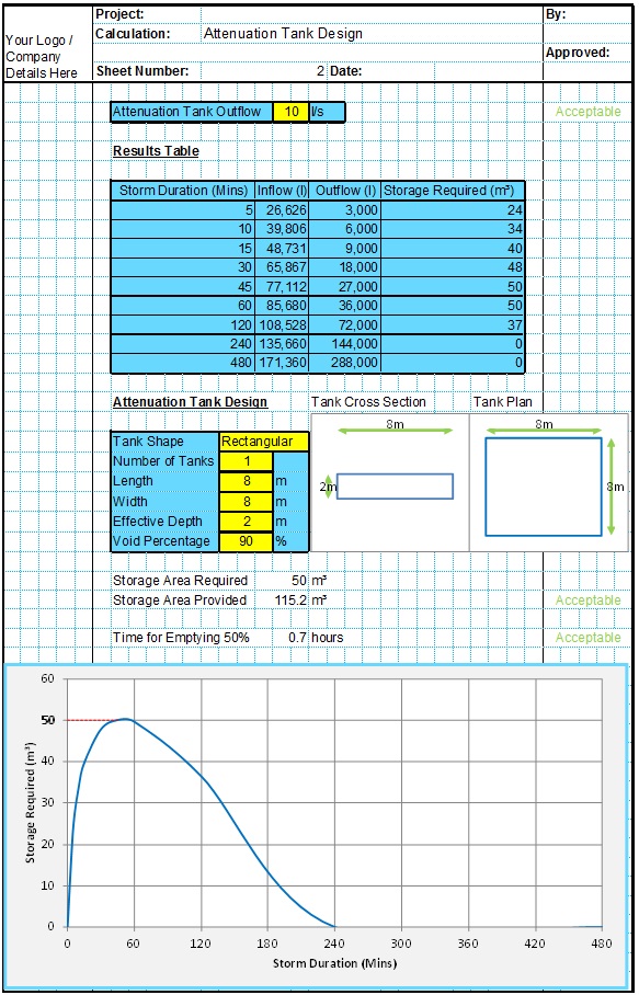
Attenuation Design Spreadsheet
This spreadsheet calculates the requirements for a attenuation system and assists the user to design a suitable system.
Runoff Calculator Spreadsheet
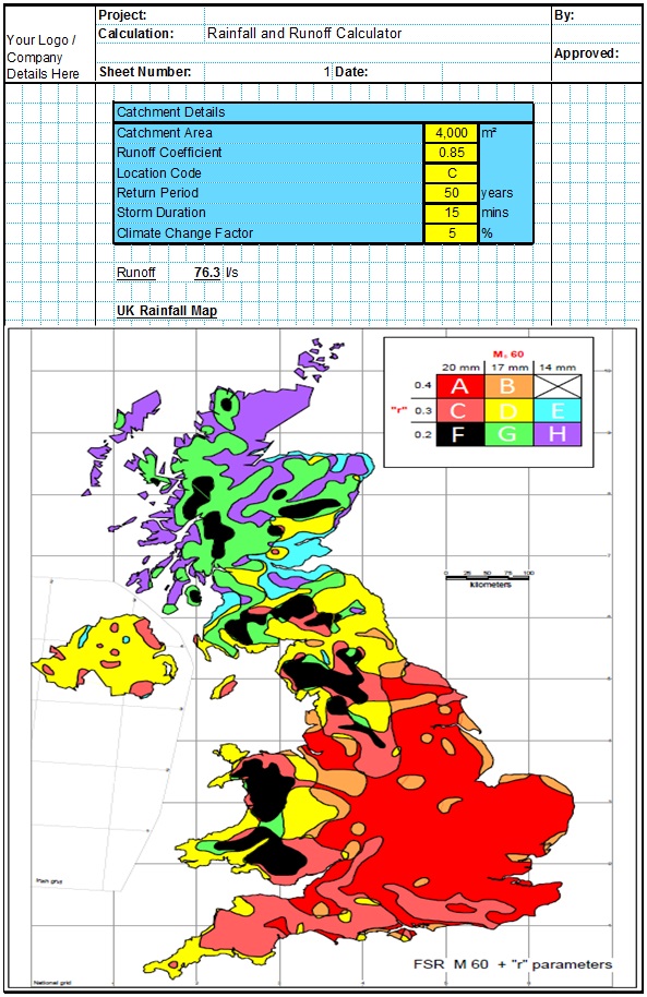
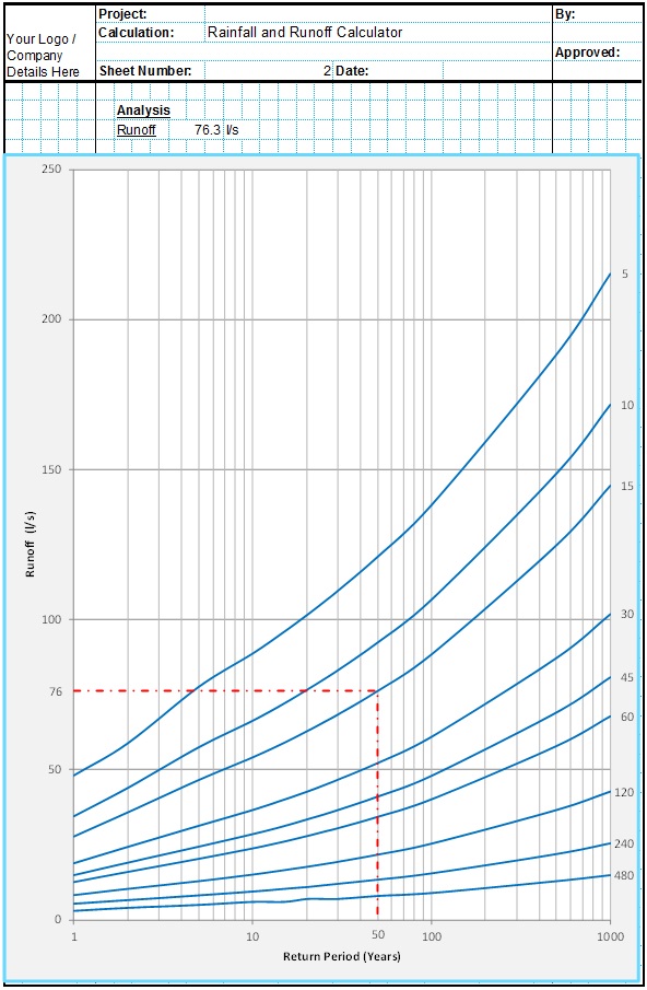
This spreadsheet calculates the design runoff flow for a site in accordance with the a number of different methods including the Wallingford Procedure.
Full Drainage Design Suite
Full drainage design suite (50% Discount) including 7 spreadsheets;
- Colebrook White Pipe Design
- Manning Pipe Design
- Manning Open Channel Design
- Linear Drainage Design
- Runoff Calculator
- Attenuation Design
- Soakaway Design
