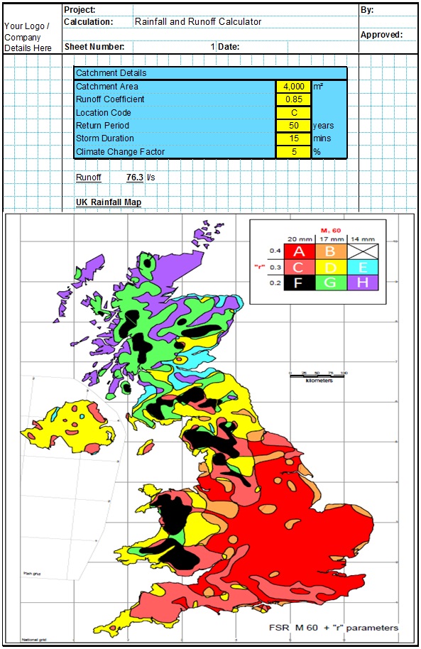
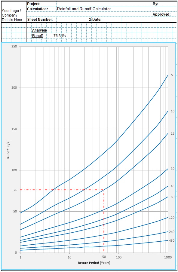
It is highly recommended that a percolation test is undertaken onsite before the detailed design of the soakaway as there is so much uncertainty involved when estimating the infiltration rate. It is specified in BS 8582 and BS 16933 that a soil percolation test should be undertaken in accordance with the procedure outlined in BRE 365 and CIRIA R156.
BRE 365 Percolation Test Methodology
The simple standard onsite soakaway test used in the UK is detailed in BRE 365. This consists of the following procedure;
- First a trench or pit needs to be excavated.
- It should be as close as possible to the proposed soakaway location and should be large enough and deep enough to provide a reasonable representation of what the proposed soakaway will be like. Infiltration tests in small pits with small volumes of water will not be representative of the real conditions and will give a misleading result. This will usually be between 1.0m and 3.0m long, 0.3m to 1.0m wide and 1.5m to 2.5m deep. Generally for catchment areas less than 100m² the pit should be at least 0.5m³, for catchment areas greater than 100m² the pit should be at least 1.0m³.
- The soakaway test pit dimensions should be measured as accurately as possible. These will be used to calculate the pit volume and internal surface areas.
- The sides of the soil infiltration test excavation should be as close to vertical as possible. The sides should be trimmed as square as possible to aid the estimation of the pit volume and internal surface area.
- Care should be taken to avoid smearing the sides or base of the infiltration test excavation. Such smearing will close the voids between soil strata and generally reduce the infiltration rates achieved during the test. Where smearing has taken place it should be removed by hand if possible.
- The soakaway percolation test pit can be filled with granular material if required for stability. If granular fill is used a perforated observation tube will need to be installed to the full height of the excavation so that seepage rates can be measure accurately. The porosity of the granular fill must be known so that the effective pit volume can be calculated with sufficient accuracy. Guidance on the porosity of typical granular fill materials is included elsewhere in this document.
- It should be practical to complete this excavation with a backhoe loader or a mini excavator.
- Small volume pits will obviously use less water during the test. They can however prove more difficult to achieve vertical trimmed sides, particularly at large depths.
- Suitable Health and Safety procedures for excavating and working around a deep excavation must be followed at all times.
- Next the soil drainage test pit must be filled with water several times in quick succession, measuring the rate of percolation in the soil.
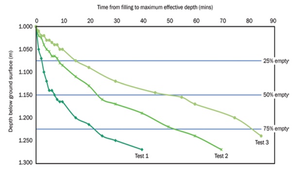
- It is important that this is done several times with the lowest seepage rate used so that the chosen design infiltration rate will replicate storm conditions when the surrounding soils will be wet. Subsequent tests can have much lower infiltration rates than the initial test, particularly when soil conditions are dry on the day of the test. This is illustrated in the below graph taken from the SUDS Manual.
- The soakaway percolation test pit should be filled to its design maximum water level and allowed to drain to near empty three times. This should be done on the same day, or on consecutive days if the infiltration rate too low to allow three consecutive tests on the same day. Alternatively a water level logger could be used to monitor the test overnight if required. Care must be taken that the excavation is suitable secured if it is to be left open unattended, particularly overnight.
- The water level should be measured at suitable time increments to allow a depth of water/time graph to be plotted, similar to the graph above. The time increments will depend on the infiltration rate of the soil, but generally at least 8-10 measurements should be taken for each test. The CivilWeb Soakaway Design Spreadsheet includes a tool to help record the tests and to plot the recorded data.
- The test often involves a large amount of water. A water bowser or similar will usually be required.
- The inflow of water into the pit should be as rapid as possible to replicate conditions when the soakaway will be at capacity.
- Care must be taken that the excavation remains stable while the test is undertaken. Particular care must be taken to ensure the stability of the sides of the excavation while the inflow water is placed in the pit. If there is concern about the stability of the excavation it can be filled with granular material as described above.
- After the tests are complete the design soil infiltration rate can be calculated.
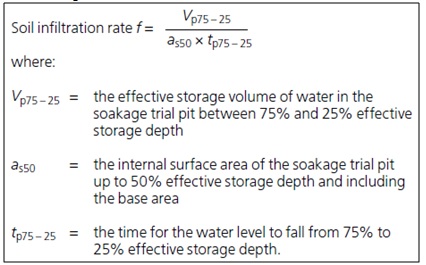
- The percolation test calculations use the following equation to ascertain the design infiltration rate;
-
- The percolation test calculation is based on the time taken for the water level to fall from 75% to 25% capacity. This is done to avoid the possible outliers of the high seepage rates when the pit is full with a large head of water, and the low rates when the pit is empty with very little head of water.
- The lowest value from the infiltration test for soakaways should be used for design, as this is likely to most closely replicate the soil conditions during a design storm event.
- The CivilWeb Soakaway Design Spreadsheet includes a tool to calculate the design infiltration rate from onsite test records.
The site should be checked to ensure that site investigation information is accurate and complete. This may include checking soil type and conditions, groundwater levels, areas of fill or contamination, condition of any nearby slopes or other geotechnical features.
Soakaway Percolation Test - Further Guidance
Typically it is important to complete a infiltration test at each soakaway location as the variation in infiltration rates across a site can vary enormously, even in fairly homogenous soil conditions.In variable soil conditions a separate infiltration test should be undertaken when the trench will be over 10m long. For long trenches, separate tests should be undertaken at roughly 25m spacings, even in fairly homogenous soil conditions. If required the results of the first test can be used to calculate a preliminary length for the trench, which will then determine how many subsequent tests will be required. If more than one test is undertaken, the average of the tests can be used as the design infiltration rate for the whole trench.
If the pit is deeper than around 3.0m it can be difficult to supply enough water to fill the pit to the design depth. If this is the case the test can still be done at less than full depth, though the calculated infiltration rates may be lower than for a full depth test. This is due to the higher infiltration rates generally achieved when there is a large head of water. For a test less than full depth, the design infiltration rate should be calculated from the time it takes for the water level to drop from 75% to 25% of the actual highest water level achieved during the test. The surface area calculation is similarly taken as the internal surface area of the pit to 50% of the actual highest water level achieved during the test, plus the base area. This can lead to a significant reduction in the infiltration rate measured. BRE 365 indicates this may be as low as 50% of the rate achieved from a full depth test.
The results of the infiltration tests can be influenced by seasonal factors. Ideally the test should be undertaken during the winter when soil moisture levels and groundwater levels are highest. Even better if the test can be undertaken after a period of rain. Where it is not possible to conduct the test under these conditions, consideration must be given to the effects of different antecedent soil conditions. The groundwater adjustment coefficient described above can also be used to judge the difference in performance during seasonal or exceptional high groundwater conditions.
Where access or depth constraints prevent an infiltration test from being undertaken or where a deep bored soakaway is considered, a falling head test can be undertaken in a borehole. This test should be done three times in accordance to the procedure in BS EN ISO 22282-2. Care should be taken when interpreting the results of these tests as they include a lot less water than the BRE 365 infiltration test. This is particularly the case if the test is undertaken in summer or dry conditions. The falling head tests could be repeated many more times in quick succession to better simulate soil conditions where there is concern or where the first three tests show a significant deterioration in the measure infiltration rate.
Results of incomplete tests should not be extrapolated. As described above the infiltration rate varies in a significant and complex manner in relation to the head of water in the pit and the soil conditions. If the water level does not drop to below 25% of the original water level this can be an indication of a high groundwater table or an issue with the infiltration rate of the soils in the lower section of the pit.
Where there is any concern regarding the veracity of the information obtained from the test, this can be taken account of through a higher infiltration rate factor of safety.
The site should be checked to ensure that site investigation information is accurate and complete. This may include checking soil type and conditions, groundwater levels, areas of fill or contamination, condition of any nearby slopes or other geotechnical features.
Related Spreadsheets from CivilWeb;
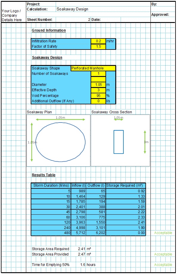
Soakaway Design Spreadsheet
This spreadsheet calculates the requirements for a soakaway system and assists the user to design a suitable system.
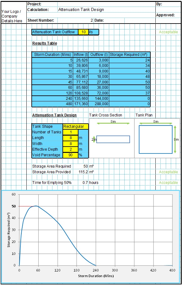
Attenuation Design Spreadsheet
This spreadsheet calculates the requirements for a attenuation system and assists the user to design a suitable system.
Runoff Calculator Spreadsheet
This spreadsheet calculates the design runoff flow for a site in accordance with the a number of different methods including the Wallingford Procedure.
Full Drainage Design Suite
Full drainage design suite (50% Discount) including 7 spreadsheets;
- Colebrook White Pipe Design
- Manning Pipe Design
- Manning Open Channel Design
- Linear Drainage Design
- Runoff Calculator
- Attenuation Design
- Soakaway Design
