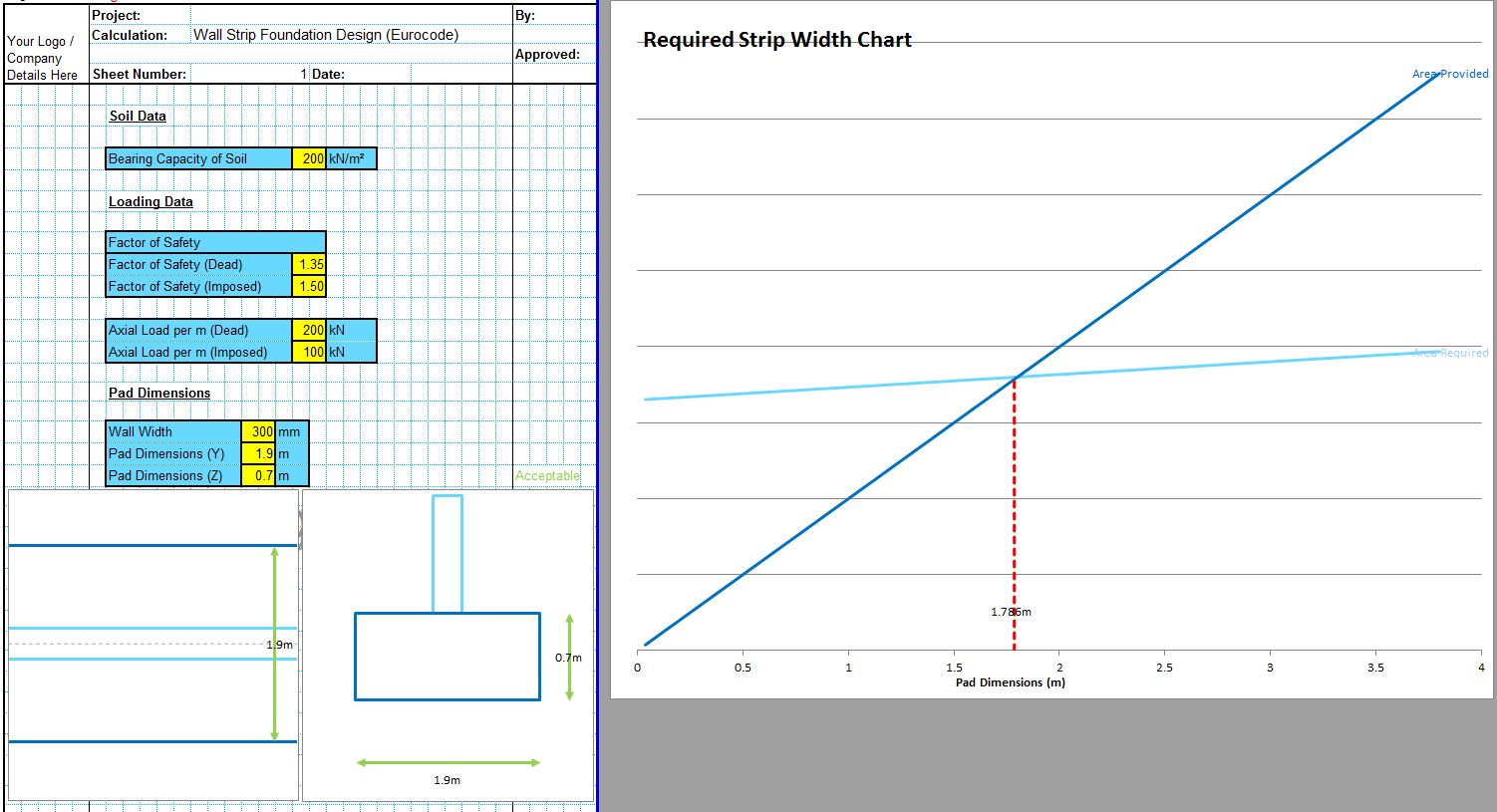
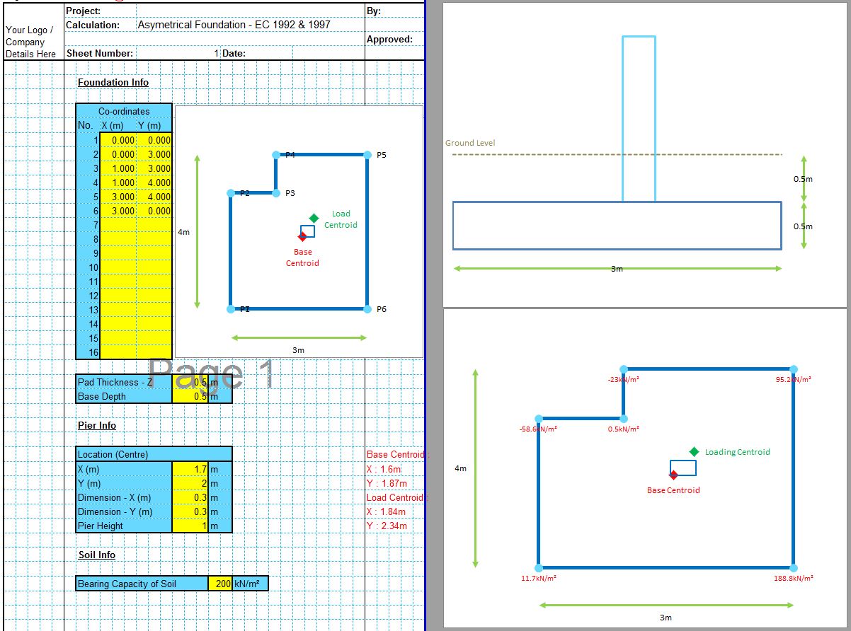
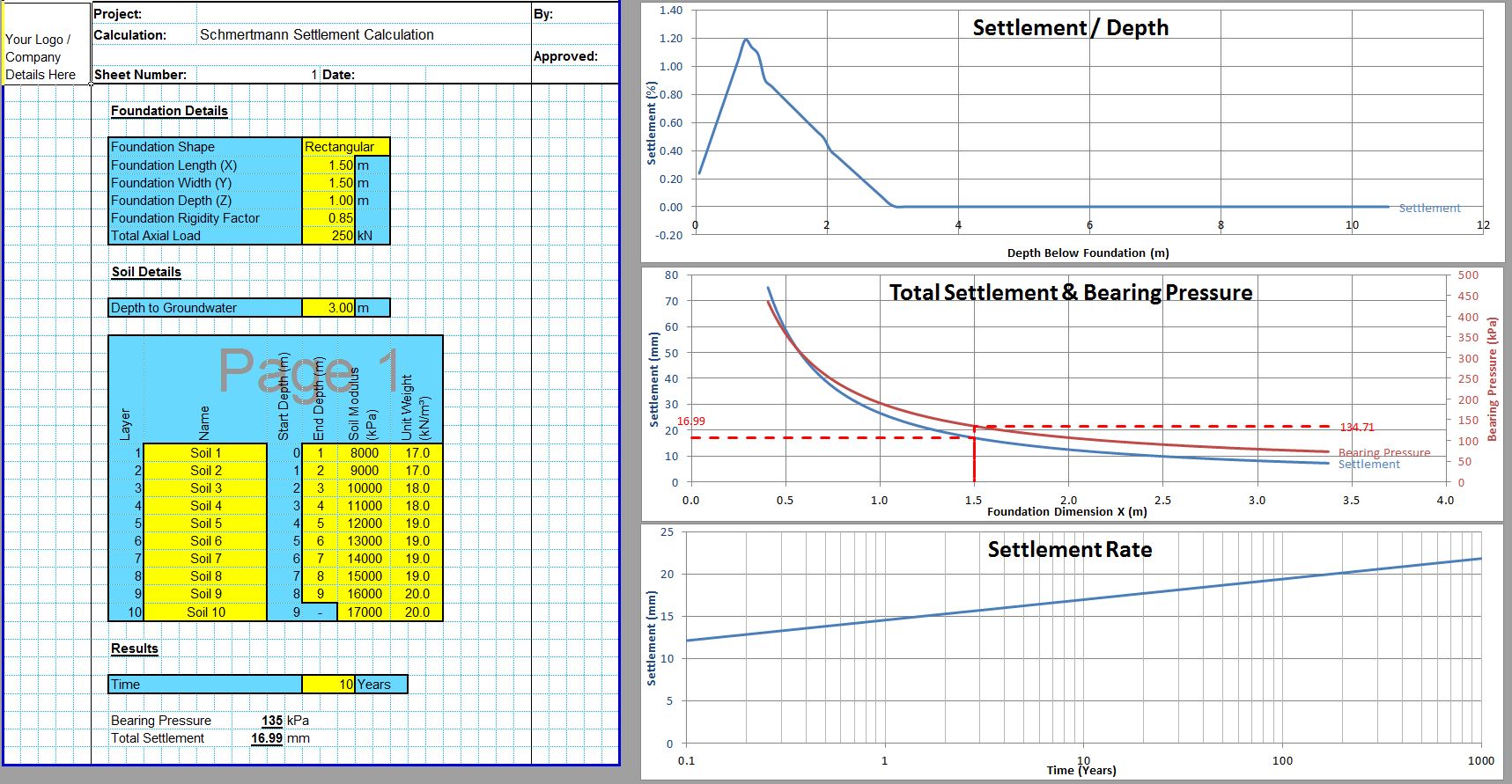
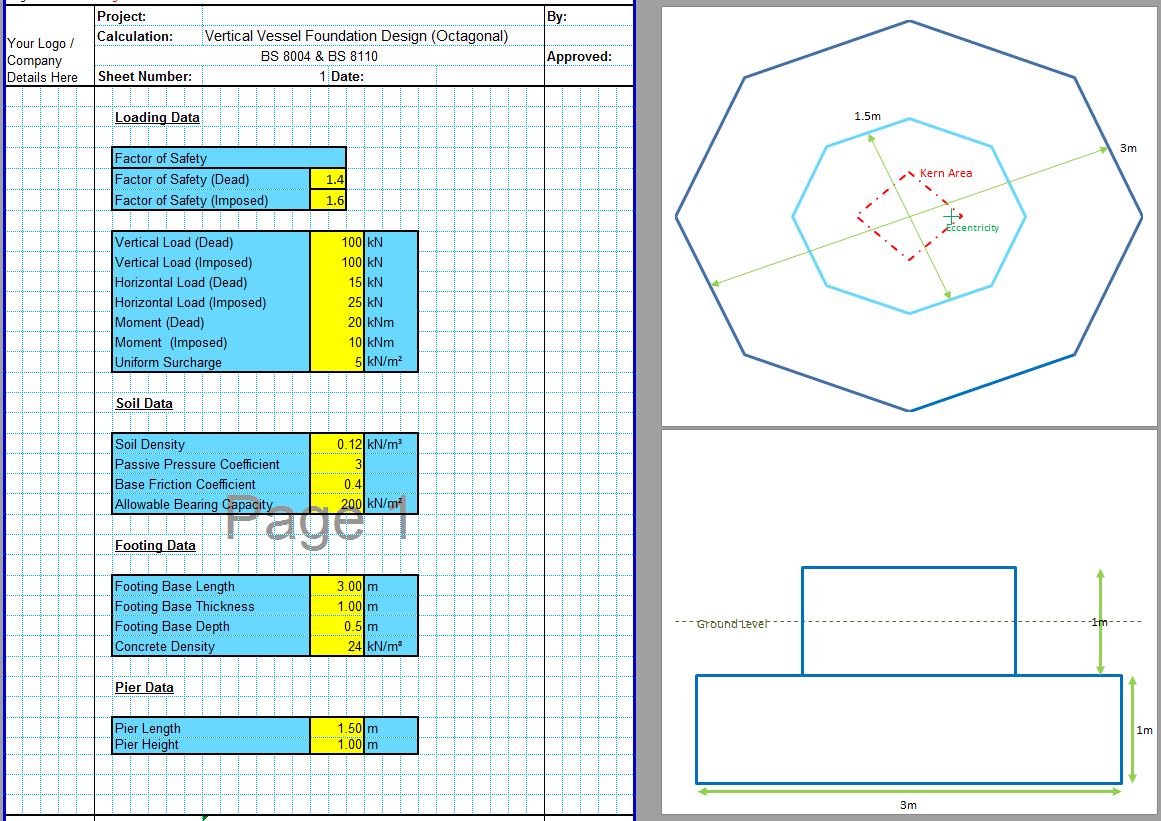
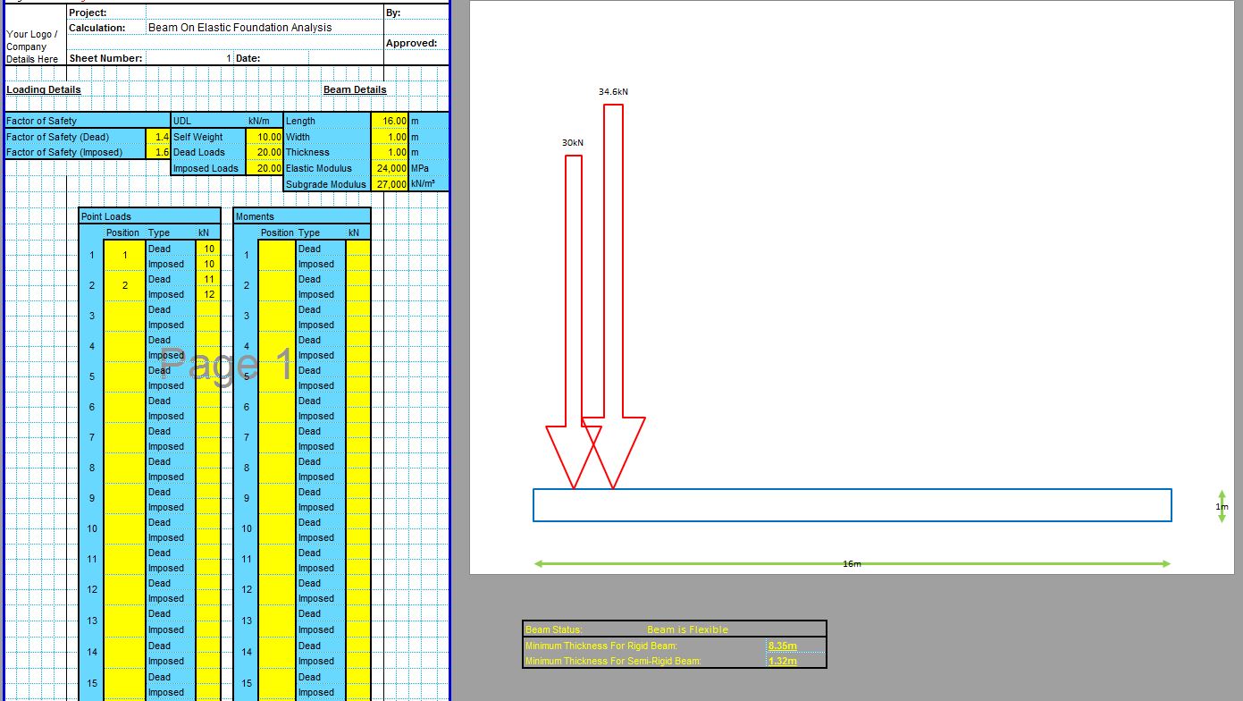
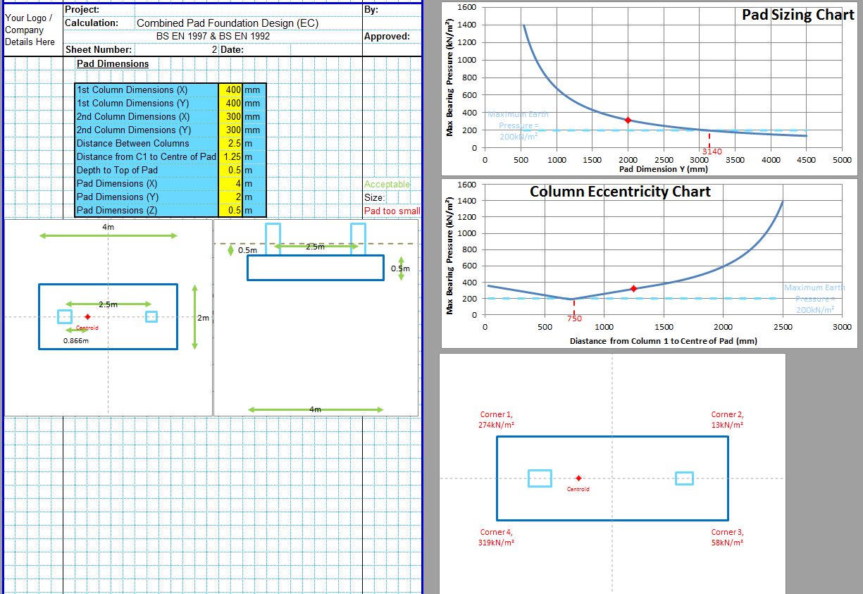
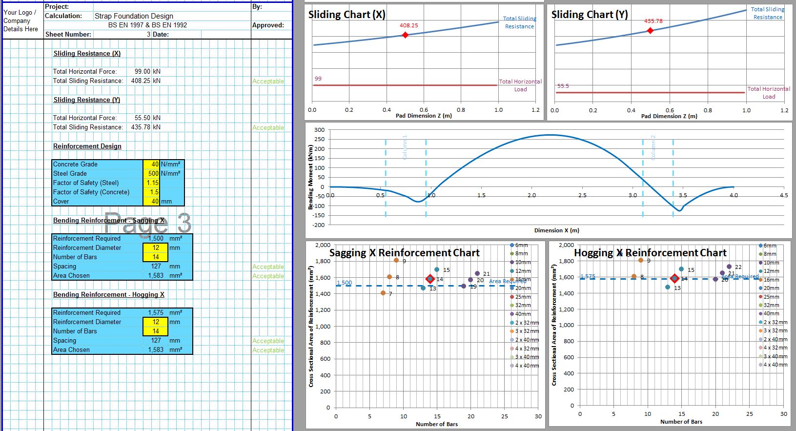
The safe bearing capacity of soils can be determined from either analytical methods or from site investigation data. The CivilWeb Soil Bearing Capacity Calculation Excel Suite includes 6 different analytical methods which use soil design properties such as its shear strength to determine the safe bearing capacity of the soil. The CivilWeb Soil Bearing Capacity Calculation Excel also includes three different methods of estimating the safe bearing capacity of the soil from site investigation results such as SPT, CPT or plate load tests. The spreadsheet suite can be purchased at the bottom of this page for only £20.
Alternatively the Bearing Capacity Suite is also included in the full Foundation Design Suite which includes all 12 of our foundation design spreadsheets for only £50. This can also be purchased at the bottom of this page.
Shallow foundations work by transmitting the forces acting on them from the structure above into the ground below. This creates both compressive and shear stresses in the supporting soils. The magnitude of these stresses depends largely on the size of the forces and the size of the foundation. So the main aim of shallow foundation design is to ensure that the foundation is sufficiently large to ensure that the forces acting on the soil are small enough for the soil to accommodate without shear failure or excessive settlement.
Types of Soil Bearing Failure
The maximum pressure which the soil can accommodate is called its safe bearing capacity. In order to calculate the safe bearing capacity of soil we must consider three main types of bearing failure.
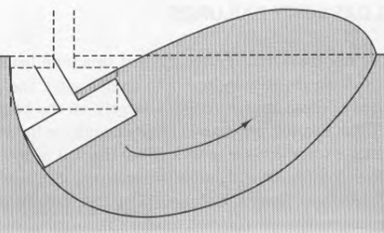
- General Shear Failure – This is the most common type of bearing failure in most soils. This type of failure is illustrated in the below diagram.
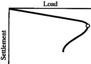
This mode of failure is usually critical in all soils which are largely incompressible with reasonable shear strength including rocks, dense sands and saturated normally consolidated clays. The failure surface for this type of failure is well defined and occurs quite suddenly. This is illustrated in the load-displacement curve for this type of failure which is shown below.
Telltale signs for general shear failure include a clearly formed bulge in the soils at either side of the foundation. The foundation usually fails on one side only and this failure is usually accompanied by rotation of the foundation. This is because of the inevitable variations in shear strength and compressibility in the soils which will cause the foundation to tilt slightly. This tilting then increases the stresses at these points which further increases the tilt and so on.
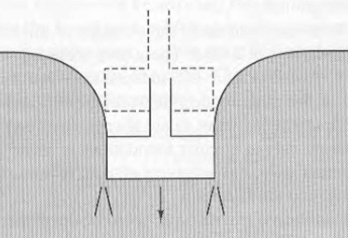
- Punching Shear Failure – This is a very local failure and tends to occur in loose sands and gravels. This failure mode also occurs in layered soils where a thin strong layer overlies a weaker layer. It can also occur in weak clays loaded under slow drained conditions. This failure mode is illustrated in the below diagram.
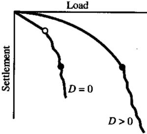
The punching shear failure mode causes large settlements and tends to occur over longer periods of time than the general shear failure mode. This is shown in the load-displacement graph presented below.
The punching shear mode of failure does not tend to show large bulges at the surface and the failure surface tends to be poorly defined vertical shear surfaces.
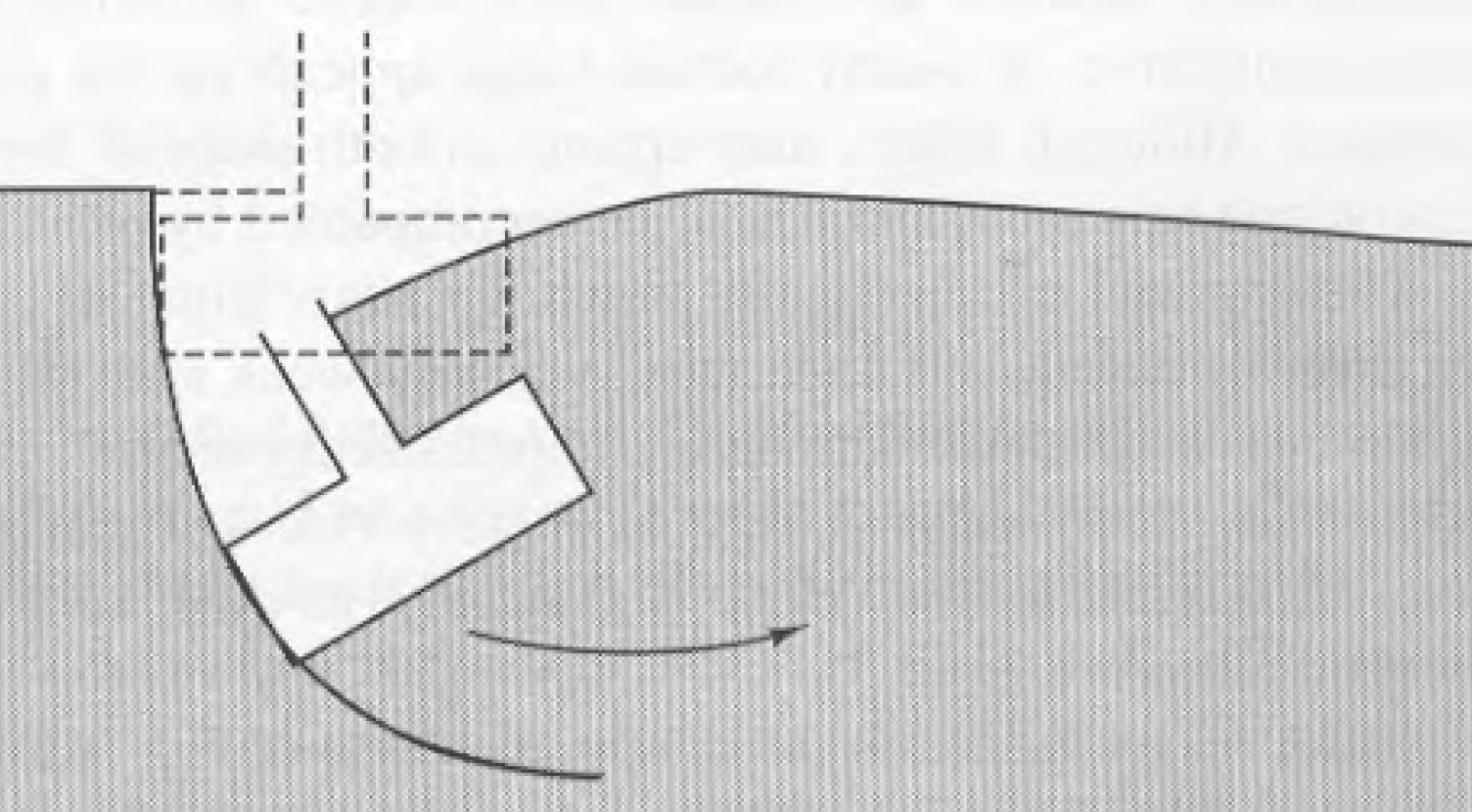
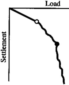
- Local Shear Failure – Local shear failure is a failure mode which lies somewhere between the sudden general shear failure and the gradual punching shear failure. This failure mode tends to be critical for medium dense sands. This failure mode is illustrated in the below diagram.
The local shear failure mode causes sustained settlement of the foundation with no clear sudden failure as occurs in the general shear failure mode. The foundation simply continues to settle as can be seen in the below load-displacement graph.
The failure surfaces for local shear failure are well defined under the foundation but become vague and unclear nearer the surface. A small bulge may occur at the surface but not as pronounced as the general shear failure mode. Settlement as large as half the foundation width can occur before the failure surface forms on the ground surface.
Which Failure Surface is Critical
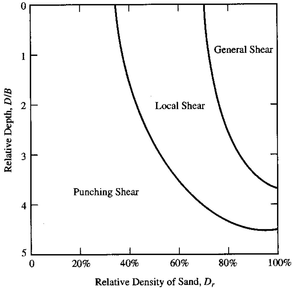
It is very difficult to determine exactly which failure mode will be critical in any soil conditions. Generally it is acceptable to assume that the general bearing capacity failure mode will be critical unless the soil consists of loose sands, drained clays or layered soil systems with weaker layers beneath stronger surface layers. The below chart was developed by Vesic based on testing of model circular foundations. This is far from conclusive however can be used as a general guide for sandy soils.
Safe Bearing Capacity of Soil Analysis - Introduction
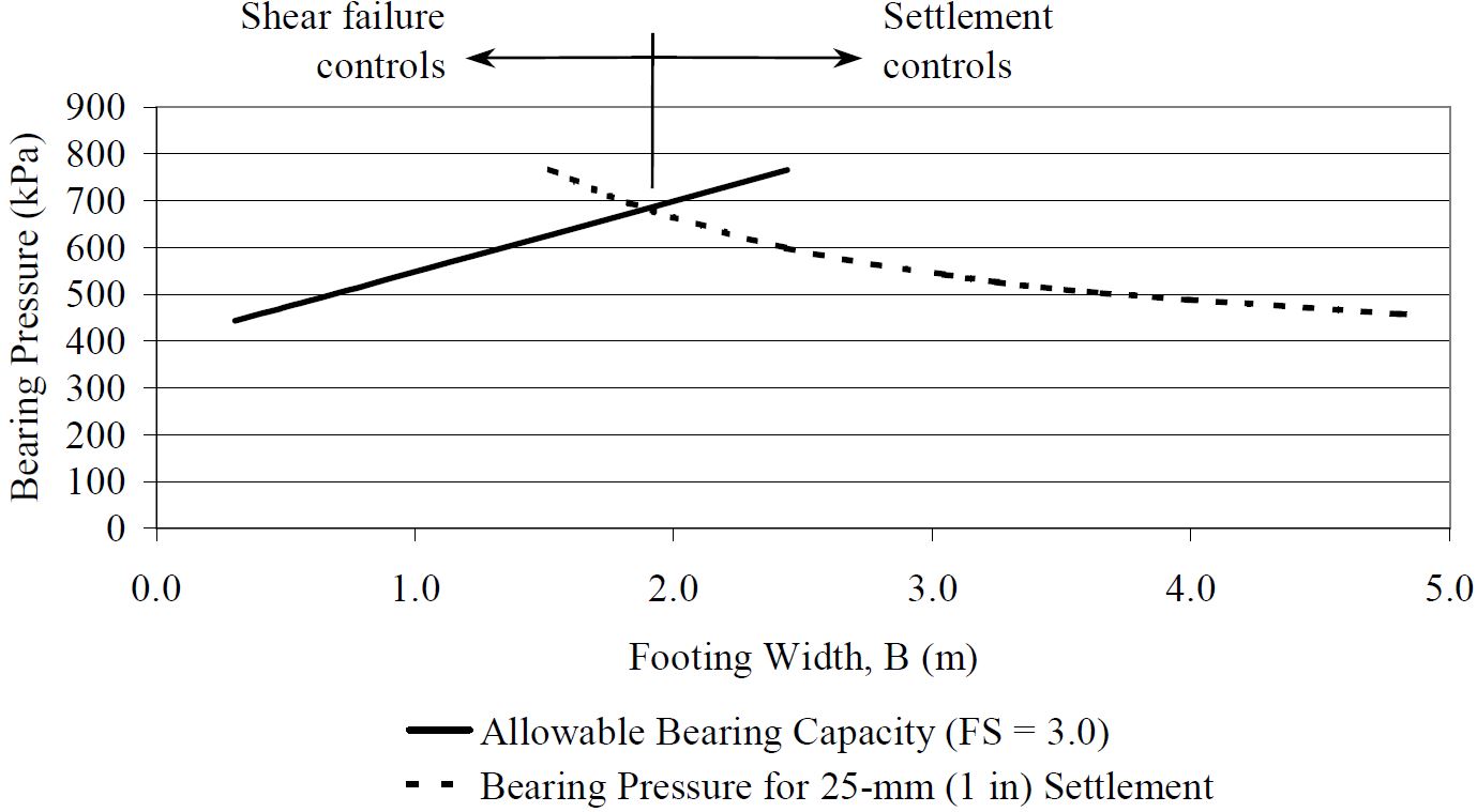
The three bearing capacity failure modes do not all need to be analysed in practice. Indeed it is difficult to model the failure surfaces of punching and local shear failures because the failure surface is not clearly defined. The general shear bearing capacity can be used for all soils so long as suitable settlement analysis is also undertaken. This will ensure that excessive settlements do not occur and implicitly protects the foundations against local and punching shear failures.
This is illustrated in the below graph which shows an example of how the safe bearing capacity of soil is superseded by settlement analysis as the foundation gets larger.
Determining the safe bearing capacity of soil in practice is very difficult. Large scale foundation load tests are the more accurate way of gauging the safe bearing capacity of specific soils however these are extremely expensive and difficult to undertake. For this reason full scale load tests are not appropriate for normal construction projects. Scale model tests are much cheaper and easier to conduct however there is some doubt as to the accuracy of this method due to uncertain scaling factors which need to be applied. This is particularly the case with scale model tests in sands.
Limit Equilibrium Analysis
The difficulties with direct testing means that the most commonly used method of bearing capacity analysis is using limit equilibrium analysis of the soils to determine the theoretical maximum bearing capacity. This method of analysis involves determining the shape of the failure surface and analyzing the stresses and soil strengths along this failure plane. This method is descended from Prandlt’s studies of the punching resistance of metals.
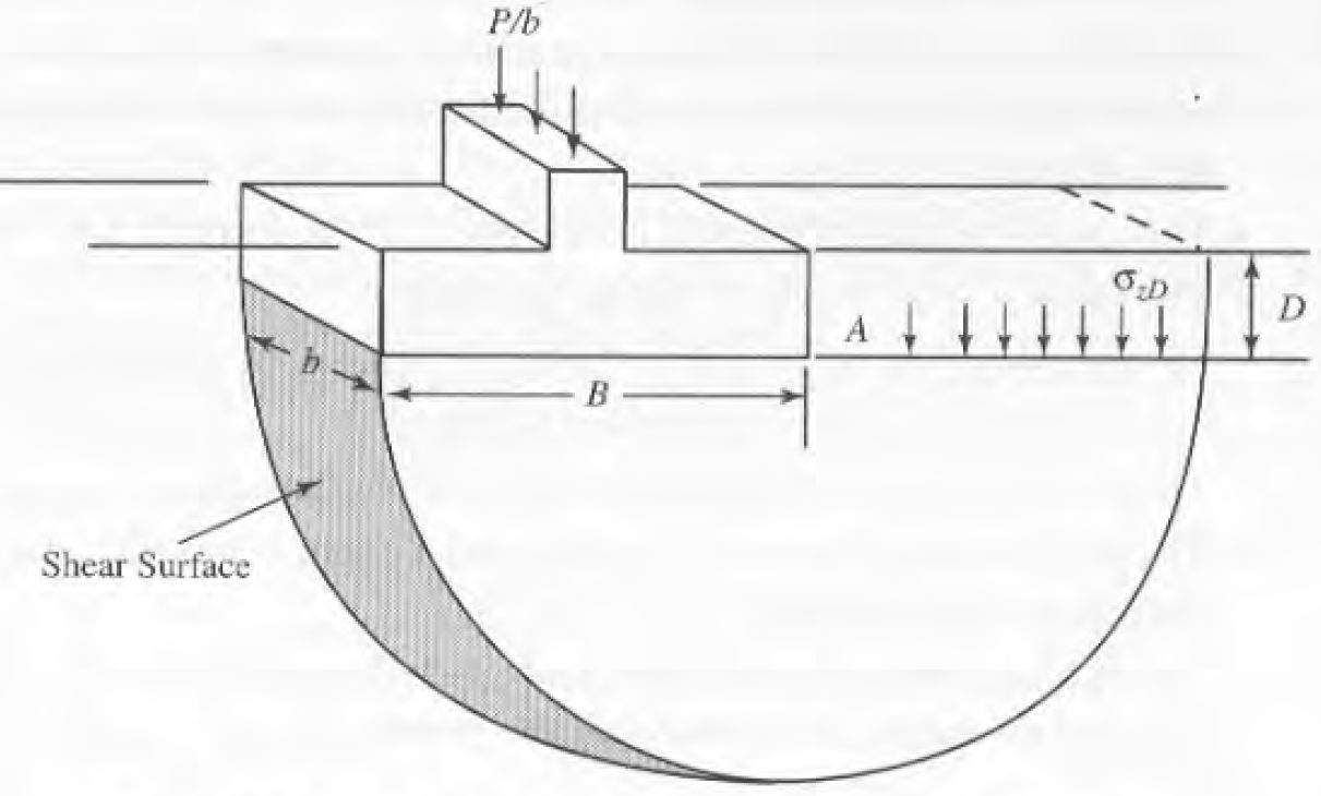
The simplest possible limit equilibrium analysis of a foundation would be a circular shear failure surface of a strip foundation in undrained soils. This is illustrated in the below diagram. The bearing capacity of this soil can be determined by taking moments about point A. If su is the shear strength of the soil and ozD is the total stress produced at depth D by the foundation load, the following equation can be derived. This forms the basis of the more complex bearing capacity equations which have since been derived in order to apply these principles to more and more foundation and soil conditions.
Which Bearing Capacity Analysis Method to Use
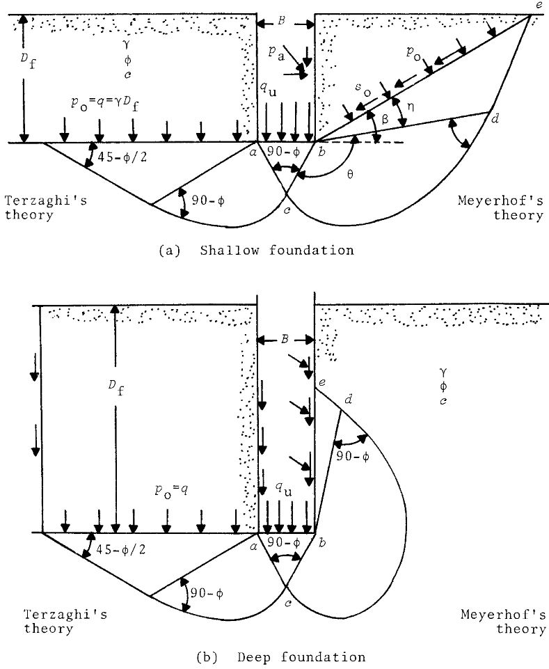
With so many different analysis methods available it can be difficult to choose which method will be most suitable for each situation. Indeed each method uses basically the same form of equation and they are all generally based on the same theory and experimental data. The only major theoretical difference is Meyerhof alters the assumed failure surface slightly to include the soil above the base of the foundation. This may or may not be appropriate depending on the design conditions. This is illustrated in the below diagram. This also shows the unsuitability of the Terzaghi/Hansen/Vesic methods for deep foundations.
The only precise way to evaluate the suitability of the safe bearing capacity equations would be to conduct a large array of full scale foundation load tests. This would however not be feasible. Where load tests or analysis of existing failed structures have been conducted the bearing capacity equations have tended to be fairly accurate, with the result a maximum of around 10% out.
In general the Terzaghi method has been extended and improved upon by the other methods so the Terzaghi method should not be used for design. Of the other methods the Meyerhof method is still used extensively in North America, which the Hansen or Vesic methods are preferred in Europe. The EN 1997-1 method and BS 8004 method are based on the Vesic method (which is very similar to the Hansen method).
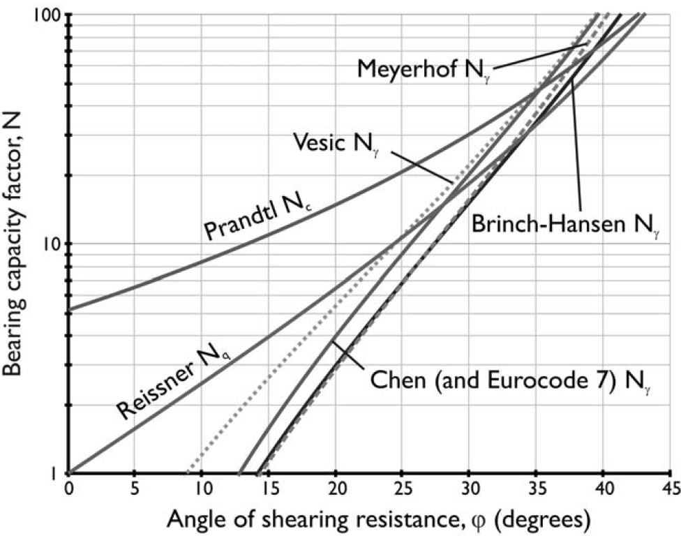
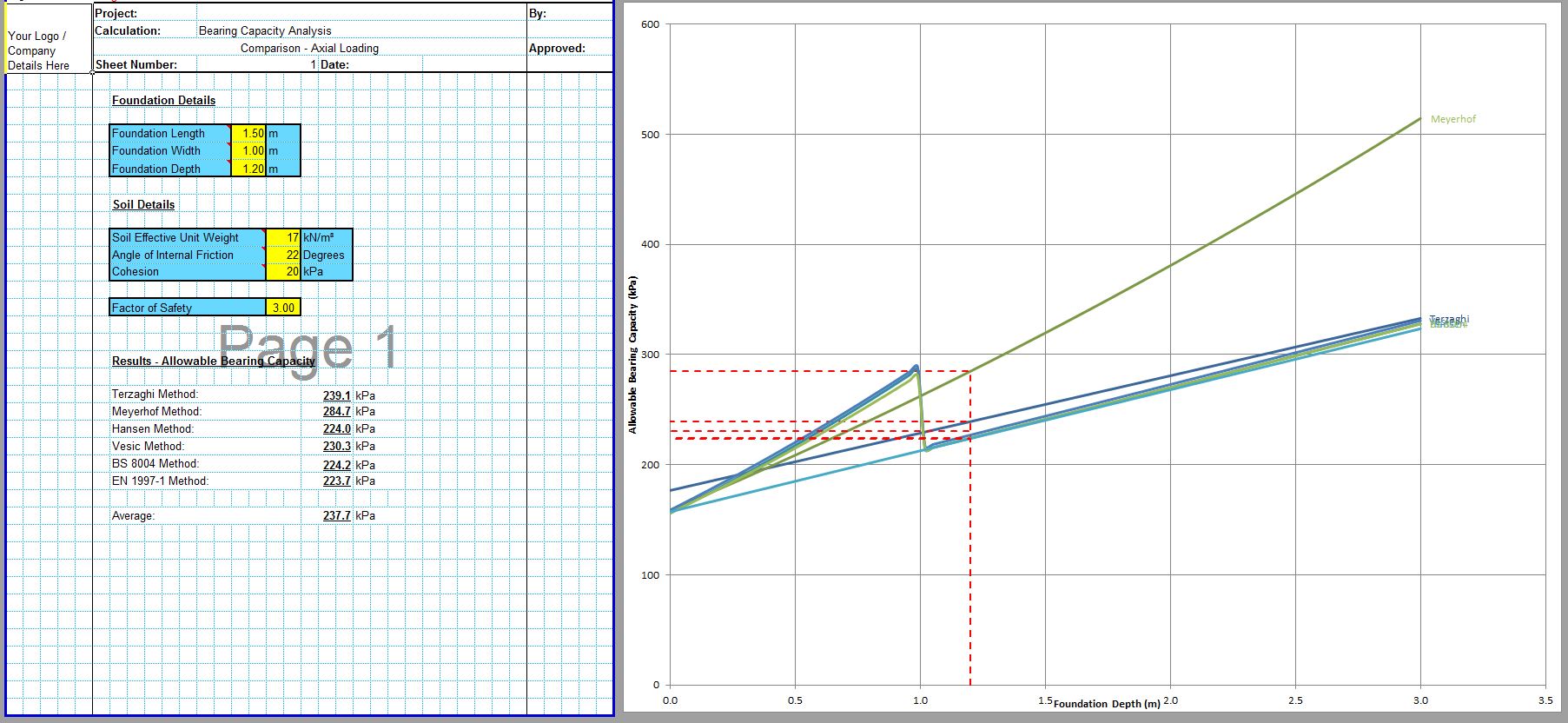
The major difference between the methods is the calculation of the Nγ value. In general the main methods are pretty closely matched, even though they all use slightly different equations. This is illustrated in the below graph.
The only cases where it is required to choose a specific method is where the design conditions make a particular method unsuitable. This is usually where a slope or a base tilt are present which may preclude the use of the Meyerhof and the EN 1997-1 methods. In this case any one of the Hansen, Vesic, or BS 8004 methods should be used.
In general it is useful to complete the calculations using two or three trusted methods to check for any anomalies. The CivilWeb Soil Bearing Capacity Calculation Excel Suite includes a unique comparison tool. This allows the designer to calculate the bearing capacity of the soil using all 6 popular analytical methods. This allows the designer to see at a glance which value is most appropriate. The spreadsheet also allows the designer to choose an average value.
Comparison with Site Investigation Methods
Bearing capacity analysis based on site tests have advantages and disadvantages compared to analytical methods. The site tests are actually testing soils insitu which can be much more reliable than laboratory results. This is particularly the case where soil deposits are very deep or where undisturbed samples are very difficult to obtain. The disadvantage with site tests is that they are not full size load tests therefore there are always difficulties with converting site test results into bearing capacities useful for full size foundations.
In general it is useful to obtain bearing capacities from several different sources and compare them. If several analytical methods are used along with a check using site investigation info such as SPT, CPT or Plate Load Test this is likely to be an accurate measure of the bearing capacities of the soil.
Accuracy and Limitations of Bearing Capacity Analysis
The accuracy of these safe bearing capacity analysis methods can be evaluated from the analysis of known bearing capacity failures as well as full scale load tests. This has been undertaken several times and the safe bearing capacities computed have typically been very close to the true values, one study in saturated clays found the maximum error to be around 10%.
Testing in sands indicates that the safe bearing capacity in sands is likely to be very high and in most cases the settlements induced before bearing capacity failure will be unacceptable. In these cases a settlement analysis will be critical, not the bearing capacity.
Soil Parameters
The greatest uncertainty for analytical methods is usually the true value of the shear strength of the soil. This is often likely to be greater than 10% from the true value, however it will be well within the usual factors of safety applied to bearing capacity analysis results.
Foundations on Sands
Granular soils will always behave in drained conditions due to the permeability of the soils so the relevant soil strength parameter is Φ’. This parameter is usually obtained through SPT or CPT testing of the soils.
Foundations on Clays
Saturated cohesive soils will generally behave in undrained conditions, so the relevant soil strength parameters are cu and Φu.
An undrained shear test can be used to calculate the cohesion and shear strength of clays for normal structures where the loads are applied relatively quickly to the foundations. This is also the case where the loading is of short duration, for example for temporary works.
This only needs to change when the rates of loading are very slow or with very silty soils where the decrease in water content and subsequent increase in shear strength could be taken into account. This might be for earth dams or similar structures which take years to build or for liquid storage tanks which can be filled slowly.
Safe Bearing Capacity of Soils - Factors of Safety
The ultimate bearing capacity calculated by analytical calculation or from site investigation information must next be converted to a safe bearing capacity for the soil. The factor of safety must be large enough to ensure that the risk of foundation failure is sufficiently low.
In general foundations are designed with a high factor of safety. This has been the case in the past due to a number of reasons;
The consequences of a bearing capacity failure can be very high. The entire structure can fail fairly quickly if the bearing capacity of the soil is exceeded. For buildings or any large structure the consequences of this failure would be very severe. Even if the problem is caught before failure, the costs and disruption of foundation repairs and improvements are usually quite high.
The reliability of the geotechnical information can be quite low. Obtaining and testing undisturbed samples of soils can be difficult or even impossible. Even if undisturbed samples can be obtained it is unlikely these will ever provide more than a snapshot of soil conditions at one particular point of the site. Soil parameters will always vary across a large site, meaning that the information input into analytical bearing capacity equations is always an average or best guess based on the information available.
The costs of extending foundations to be larger than they might need to be are usually relatively small as a proportion of the total costs of a project. Foundations might be 5% of the cost of a large building. It is usually prudent to slightly increase the depth and size of foundations rather than accept a higher risk of foundation failure.
Typical Factors of Safety for Safe Bearing Capacity of Soil
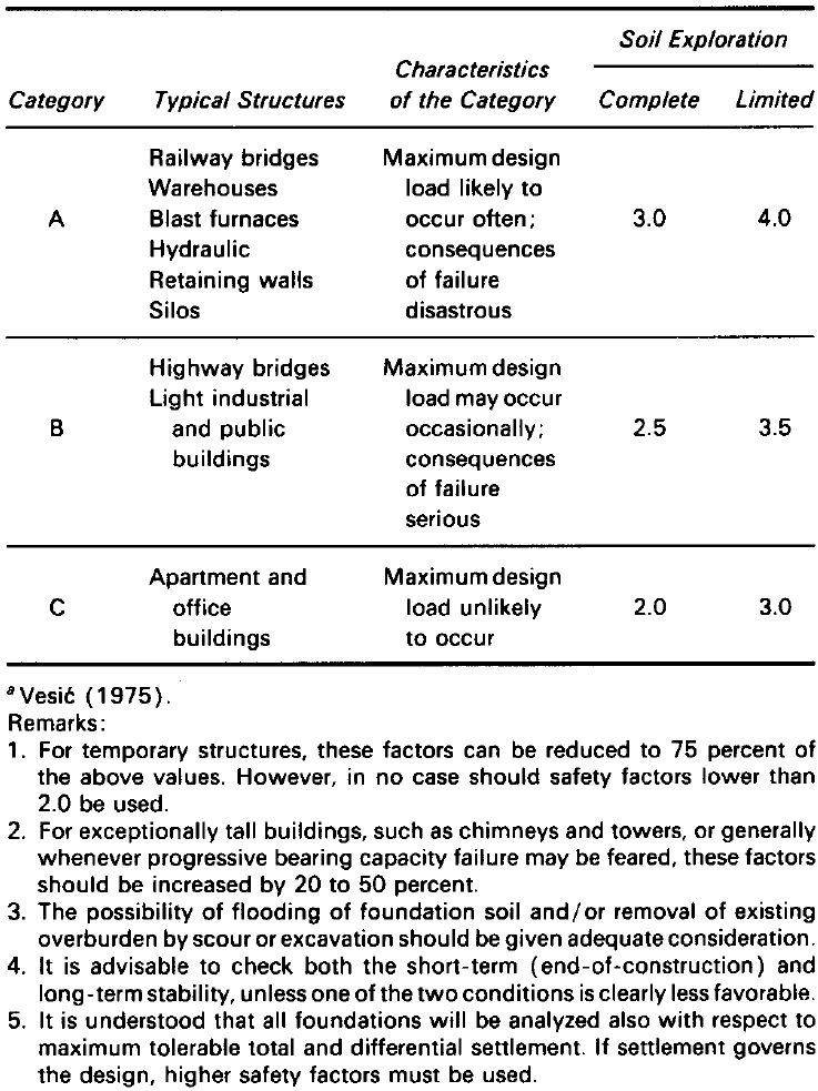
Typically the factors of safety used for bearing capacities for foundations are taken between 2.5 and 3.5, with 3.0 being most commonly used. This provides a very high confidence that the bearing capacity of the soil will not be exceeded so long as the design has been carried out correctly. One example of typical factors of safety for different structures is shown below.
Some local or national standards may specify minimum factors of safety for foundations and bearing capacities. These should always take precedence. Eurocode design should be undertaken using partial factors rather than a single factor of safety.
Choice of Bearing Capacity Factor of Safety
The choice of the factor of safety for a particular project depends on many factors, some of which are detailed below.
Soil Type. The shear strength of clay soils is generally less reliable than the strength of sandy soils. More failures tend to occur in clay soils, so a higher factor of safety may be justified in clay soils.
Quality and Quantity of Site Investigation Information. It is normal for the preliminary design of foundations to begin before much site investigation information has been undertaken. In these cases the lack of information must be accounted for either in the choise of soil strength parameters or in the factor of safety. When detailed design is undertaken the quantity and quality of site investigation information should be accounted for. Again this can be done either in the designer’s choice of soil strength parameters or in the factor of safety, or both.
Soil Variability. Some sites will be fairly uniform which suggests that the site investigation information provided is more reliable. Other sites however can vary a great deal both from one side of the site to the other and also in localized pockets within the site. Where site investigation information suggests that the soil characteristics of the site may be variable, the designer may choose to allow for this variability with a higher factor of safety on the bearing capacities.
Consequences of Failure. As discussed the consequences of foundation failure are usually quite high or very high. However there will be lots of cases for isolated unoccupied structures such as agricultural buildings or other isolated structures where foundation failure would be unlikely to present a risk to life. In these cases a smaller factor of safety may be justified, particularly where a larger factor of safety would significantly increase the construction costs.
Size and Height of Structure. Large and high structures such as chimneys and towers are more likely to experience a sudden bearing capacity failure than smaller structures. A larger factor of safety may be deemed necessary for high structures.
Temporary or Permanent Works. The likelihood of failure depends on the amount of time that a structure will be in place. Temporary structures such as falsework or foundations for construction plant or cranes may use a smaller factor of safety to account for the fact that the foundation will not be in use for a long period of time.
Likelihood of Design Loads Occurring in Practice. Some structures such as residential or office buildings are designed with relatively high design loads which are unlikely to ever happen in real life. Other structures such as silos or dams are very likely to experience their design loads regularly over their life. A lower factor of safety might be considered in some cases where the design loads are deemed to be unlikely to be realized.
The actual factor of safety is also likely to significantly exceed the design factor of safety. Soil strength parameters are usually interpreted conservatively, design loads are often higher than actual service loads and analytical equations usually contain assumptions and simplifications which err on the conservative side.
CivilWeb Soil Bearing Capacity Calculation Excel Suite
The CivilWeb Soil Bearing Capacity Calculation Excel Suite includes 9 popular methods of determining the safe bearing capacity of soils making the spreadsheet suitable for any bearing capacity design. The spreadsheet includes unique analytical tools allowing the designer to complete a fully optimised design in minutes.
Buy the CivilWeb Soil Bearing Capacity Calculation Excel Suite now for only £20.
Purchase the our Soil Bearing Capacity and Settlement Calculation Bundle for only £25.
Or buy our best value bundle, the full Foundation Design Suite including all 12 of our foundation design spreadsheets at a discount of 80%.
Download Free Trial Version
To try out a fully functional free trail version of this software, please enter your email address below to sign up to our newsletter.
Other Foundation Design Spreadsheets;
Foundation Design Spreadsheet Suite
Our full Foundation Design Suite includes all 12 of our foundation design spreadsheets for only £50 (80% discount).
