The CivilWeb Cathodic Protection Design Spreadsheet includes unique design tools to assist the designer in completing a fully compliant anode design. This includes tools to assist calculating the steel area, automatic current demand calculations in accordance with DNVGL-RP-B401 and a unique anode optimization tool which calculates precisely the most economical anode design possible based on the designers inputs. There is nothing currently on the market which can complete the optimization process faster.
Steel Area to be Protected
The first calculation to make when designing a new cathodic protection scheme is to determine the surface area of the steel structure to be protected. This determines the amount of anodic material required for the design.
While all steel surface area calculations will obviously be very specific to the structure being protected, the CivilWeb Cathodic Protection Design spreadsheet includes some tools which can be helpful in determining the surface areas for typical harbour structures. The spreadsheet includes calculation tools for tubular piles, Rendex or Rectangular piles made from sheet pile sections, and a linear feature or sheet pile wall calculation tool.
When a large structure is considered, there may be several sections of steel which are not electrically connected to each other. In this case each section must be designed separately to ensure that all parts of the structure are suitably covered. Care must be taken when calculating the steel areas that the structure is split into suitable sections.
Current drain must also be considered where structures not included in the design will be electrically connected to the structure being protected. This may be either temporary or permanent electrical connections. Also where steel piles are to be left open the internal surface area of the pile must be included to a depth of 5 times the pile diameter to allow for the current drain.
Anode Design - Current Demand
Firstly the current demand that the structure will put on the cathodic protection system must be calculated. This is the product of the total surface area of the structure including any current drains and the current density. The current densities required for this calculation can be taken from past experience or typical values are given for different locations and environmental conditions in various international standards. The current demand is calculated for three design phases, initial, maintenance and final which cover the three most important phases of the cathodic protections design life.
Anode Design
When the current demand is known, next the anodes must be designed to provide this current at the three design phases. The current provided by the anodes is dependent on the protection potential, the anode closed circuit potential and the anode resistance to the electrolyte. This is critical for the initial and final phases where the anodes must be capable of providing enough current to polarize the structure.
The protection potential is the potential which the system must maintain to protect the structure from corrosion. This is different for different metals and can depend on environmental conditions.
The anode closed circuit potential is dependent on the precise composition of the anode alloy. This should be taken from the anode supplier based on long term electrochemical tests. If this information is not available or for preliminary design typical values are given for different standard anode alloys in various international standards.
The anode resistance to the electrolyte is dependent on the type and the dimensions of the anode and the resistivity of the seawater. Equations are given for the resistance of different anode types based on their geometry. Note that this must be done for the initial and final phases, as the anode geometry will change as the anode is depleted over its design life.
The resistivity of the seawater can be taken from experience of similar structures in the same location or must be measured to get an average value. This may change based on the state of the tide or on seasonal variations so many separate measurements may be required to get an average value. Where these measurements are not practical or for preliminary design, typical values can be ascertained from international standards based on the temperature and salinity of the water.
The maintenance phase requires a much lower current demand but is the case for the majority of the cathodic protection systems design life. Therefore the anode must be massive enough to maintain this current demand for the design life of the system. The anodes capacity to deliver this current is dependent on its total volume and density and the electrochemical capacity of the anode alloy. The anode electrochemical capacity must be taken from the anode supplier and must be based on long term testing undertaken in similar environmental conditions at a similar current density. Where this information is unavailable typical values can be taken from international standards.
Anode Design
Once the total required current densities at initial, final and maintenance stage are known, the total current required can be calculated by multiplying the required current density with the area of steel. This must be done for immersed and buried steel sections separately and then added together to get the total current required at each stage.
Anode Design - Calculations
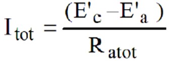
Next the anodes must be designed to provide the required current at all stages of the design life. The current provided by each anode is equal to the Driving Voltage divided by the Anode Resistance to the electrolyte (Ratot), as shown in the below equation;
Driving Voltage (E’c – E’a)
The anode driving voltage is equal to the Protection Potential (E’c) minus the Anode Closed Circuit Potential (E’a).
Anode Design and Specification
There are other important factors to consider when designing a cathodic protection system, such as those below.
Anode Composition – The precise composition of the anode alloy is important for its electrochemical capacity and should be specified to suit the environmental conditions and the electrochemical requirements of the design. There are many suitable typical anode alloy compositions specified in international standards.
Anode Spacing – Anodes should spaced as evenly as possible over the structure to prevent interaction and shielding effects from locally reducing the protective potential.
Anode Inserts – The steel inserts inside the anode hold the anodic material together and are used to fix the anode to the structure. The inserts must be large enough to withstand the forces expected to act on the anode and be suitable to attach to the structure.
Anode Fixings – The anodes must be fixed to the structure in a suitable manner which is robust enough to ensure the anodes are safely attached to the structure for the design life of the system. They must also ensure electrical continuity with the structure is maintained over the cathodic protection systems design life.
Anode Manufacture, Inspection and Testing – The anodes must be manufactured in accordance with international standards in order to ensure they perform as designed. Inspections and tests of the completed anodes must be done to ensure quality and to check electrochemical performance.
Compatibility with Coatings – Anodes are often designed to work alongside coating systems. Care must be taken that the coatings are compatible with the cathodic protection system. Coating breakdown factors are used to estimate the requirements of the cathodic protection system when working alongside a coating system.
Hydrogen Induced Stress Cracking – Cathodic protection can cause HISC in some structural materials. This should be checked before a cathodic protection system is designed.
Potential Surveys – A survey of the structures potential must be undertaken shortly after installation to check that the cathodic protection system is operating as designed.
Anode Design and Optimization
After all of the above have been completed the type, size and number of anodes required can be optimized to suit the initial, final and maintenance stages. This can be very time consuming, particularly if the calculations are to be done by hand. The CivilWeb Cathodic Protection Design spreadsheet includes very useful tools to make this optimization process as quick and easy as possible.
Firstly the user must input the type of anode to be used along with the design data for the particular alloy used. This info includes the materials electrochemical capacity, density and closed circuit potential.
Then the user must input the total number of anodes to be used in the system. This is usually determined by the type of structure being protected, for example a structure of tubular steel piles will usually include between 1 and 8 anodes per pile. A steel sheet pile structure will often include a maximum of 1 anode per inpan.
The spreadsheet then calculates the total mass required for the system to protect the structure for the full design life. Next it calculates the anode length required for the system to fulfill the initial and final stage current demands. Anode length is the most critical factor for these stages, the spreadsheet assumes that the anode width and depth are equal and that the dimensions are altered with the length to suit the overall anode mass required. This produces two graphs which show the length required to fulfill the initial and final stages while optimizing the total mass of anodic material used. A third graph is then created which shows the minimum width and depth to fulfill the overall mass requirement of the maintenance stage.
With this information the designer can instantly see the optimum anode dimensions and a summary of the optimum anode dimensions is shown. Where these dimensions are too large or small to be practical, the user must alter the total number or type of anodes until a practical solution is obtained. Generally it is more economical to install a smaller number of large anodes than a large number of smaller anodes.
Anode Dimensions and Details - Anode Length
The length of the anode is the most critical factor determining the maximum current output the anode can achieve during the initial and final polarization stages. While it is generally economical to specify a smaller number of long anodes, for many applications a maximum length of around 3.0m is standard and specifying anodes longer than this may not be practical in many cases. For this reason the CivilWeb Cathodic Protection Design spreadsheet will highlight any designs specifying anodes longer than 3.0m.
Different Sized Anodes
Wherever possible the same sized anodes should be used on a particular structure. This is because where there is a discrepancy in the ratio between the anodes current output and the anode mass, the smaller anodes will be more rapidly consumed than the larger anodes. This can lead to the smaller anodes being completely consumed before the overall design life leading potentially to a reduction in protection. No single anode should have a ratio more than 50% higher than any other anode protecting the same structure.
Anode Spacing
Anode must be sufficiently spaced out along the structure to prevent interaction effects between anodes which can reduce the useful current output.
If the required number of anodes can be spaced fairly uniformly over the protected structure this should not be an issue as this will achieve a uniform current distribution. Only where there are high concentrations of exposed steel surface areas in proximity or where there are restrictions on where the anode can be placed can this become an issue. In these cases finite element or boundary element modelling can be useful.
Generally shielding and interference effects become insignificant at a spacing of around 0.5m. If interference is suspected, a conservative approach would be to consider the two anodes as one long anode, or one wide anode depending on their location in relation to each other.
Attenuation Formula
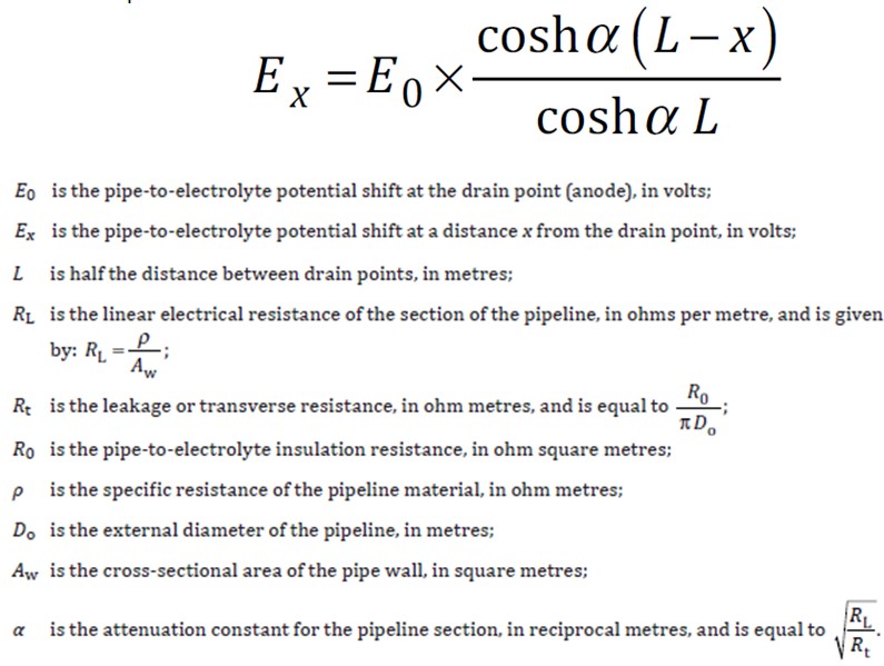
There are a number of simplified equations which can be used to estimate the steel potential at any point along simple linear structures such as steel piles or pipelines. The CivilWeb Cathodic Protection Design spreadsheet includes a calculation tool which uses the Morgan formula as presented in ISO 15589-2.
Anode Steel Inserts
The anodes are attached to the structure using steel inserts which run through the anodic material. The connection must be robust enough to withstand any anticipated wave loadings and must ensure that the anode remains electrically connected to the structure. Measures to ensure electrical continuity are included here.
Typically anodes use a steel rod or insert running through the anodic material which can be easily attached to the structure and will maintain electrical continuity with the anodic material. The steel inserts must be compatible with the structure it will be welded to.
The steel inserts must be blast cleaned to Sa 2.5 according to ISO 8501-1 before casting. Alternatively for zinc anodes the steel insert can be galvanized according to ISO 1461.
For long or short slender stand-off type anodes the insert should preferably be cylindrical. This avoids the risk of gas entrapment under the bar during the casting of the anode. The size of the insert should be determined based on the weight of the anode to be supported and the loading and environmental conditions expected.
For flush mounted anodes the insert should be made of flat or angle bars. The inserts will protrude from the anode in a way which allows them to be connected to the structure.
Insert Design
The inserts should be designed with the following loading conditions considered;
- Pre-service conditions such as loads induced during casting, handling and transportation.
- Loads induced during the construction of the structure such as the fabrication of the structure and any expected pile driving conditions.
- Motions and accelerations of anodes installed on moving parts or moving structures.
- Wave slamming forces, particularly for stand-off type anodes installed in the wave zone.
- Fatigue induced from pile driving activities or from wave forces should also be considered. A procedure for assessing fatigue produced during pile driving is given in BS EN 12495.
After designing the insert it should be checked that the anodic material/steel ratio is adequate to prevent the risk of cracking during casting. Generally for cylindrical or rectangular cross section anodes between 100mm and 150mm a steel insert of 25mm diameter is typically used.
The detailed anode insert design shall ensure that the inserts are not significantly exposed and will continue to support the remaining anodic material when the anode has reached its design utilization factor. Any deviation for the typical utilization factors presented elsewhere in this document should be highlighted to the designer at an early stage as this will impact on the design life of the cathodic protection system.
Manufacture
Insert materials should conform with the requirements of NACE standard SP0387. Inserts for welding to the protected structure should also be traceable to a certificate according to BS EN 10204 or ISO 10474. Individual anodes should also be traceable to the corresponding welding certificates.
All fabrication welding of anode inserts shall conform with the requirements of NACE standard SP0387 and should include a visual inspection just before the casting of the anode. This should conform with the manufacturer’s Manufacturing Procedure Specification (MPS).
Testing
The positions of protruding anode inserts should comply with the tolerances stated by the manufacturer. This should be checked for a minimum of 10% of the anodes of each design. This may be extended by the purchaser if required.
The acceptance criteria for steel inserts should be ±5mm for bracelet and flush mounted anodes, and ±10% of the anode thickness covering the insert for stand-off type anodes.
A minimum of two anodes of each size should be subject to destructive tests to verify the location of anode inserts.


