Often the first design verification check is for bolt failure. These checks ensure that the anchors bolts proposed are strong enough to take the tensile and shear loads expected without failing. The CivilWeb Concrete Anchorage Design Spreadsheet completes the necessary calculations in accordance with BS EN 1992-4.
Steel Bolt Failure – Tension
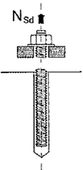
The first verification is for the tensile strength of the steel bolt itself. It must be ensured that bolt failure does not occur, ie the steel bolt is strong enough to resist the tensile forces imposed on it. The bolt failure mode is illustrated in the diagram below. This verification is required for all anchors, cast in anchors, mechanical anchors and chemical anchors.
Tensile Bolt Failure - Design Verification Calculations
To ensure that the steel bolt does not fail in tension, the tensile strength of the steel provided must be greater than the tensile force, as shown in the below equation;
This states that the Tensile Force on Each Bolt (NEd) must be less than or equal to the design tensile resistance of the bolt (NRd,s), which is equal to the Characteristic Steel Resistance (NRk,s) divided by the Partial Safety Factor for Steel Failure (γMs).
Tensile Force on Each Bolt (NEd)
This can often be taken as the total tensile force on the fixture divided by the number of bolts. For asymmetrical fittings an assessment must be done to ascertain the load on the most heavily loaded bolt.
Characteristic Steel Resistance (NRk,s)
This is a multiple of the cross sectional area of the bolt (As,nom) and the bolt tensile strength (RM).
Bolt Cross Sectional Area (As,nom)
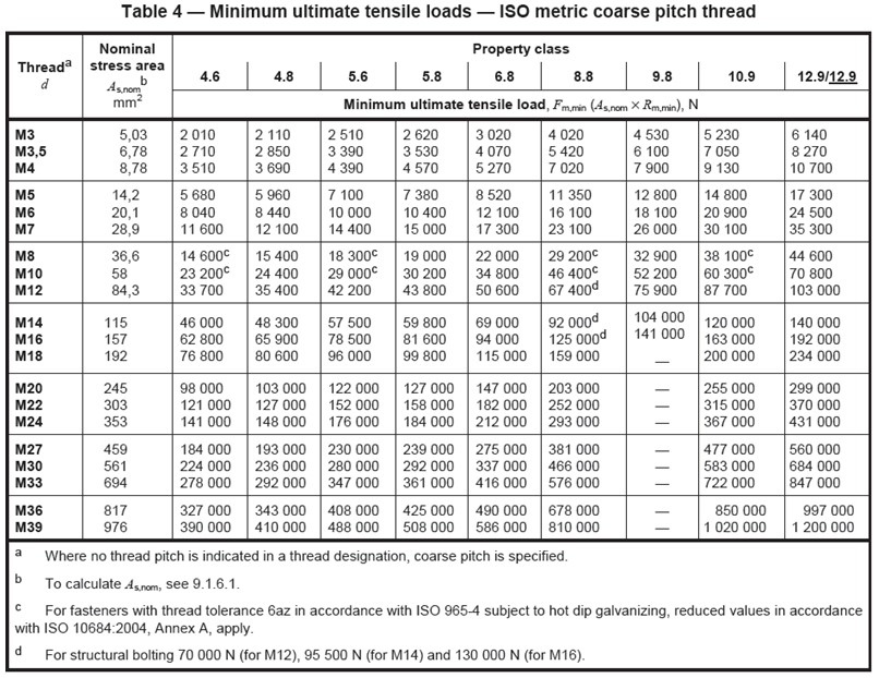
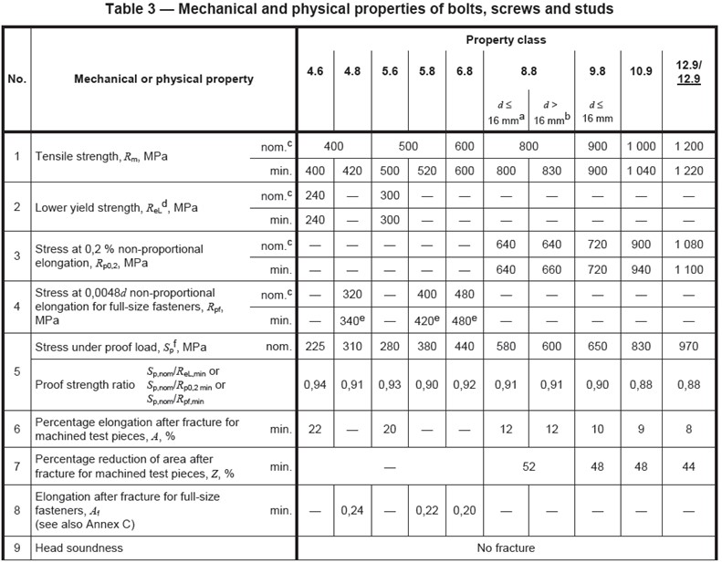
This can be calculated from the diameter and thread depth of the bolt, or can be taken from standard tables such as ISO 898-1 shown at the bottom of this page. The CivilWeb Concrete Anchorage Design Spreadsheet uses info taken from ISO 898-1 but this can be manually overridden for customized bolts.
Bolt Tensile Strength (RM)
The tensile strength of the bolt can be taken from the manufacturer or from applicable national standards, such as ISO 898-1 shown at the bottom of this page. The CivilWeb Concrete Anchorage Design Spreadsheet uses info taken from ISO 898-1 but this can be manually overridden for customized bolts.
Partial Safety Factor for Steel Failure (γMs)
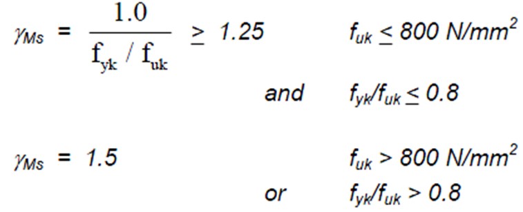
This partial safety factor is calculated using the below formula which depends on the tensile strength of the bolt. The CivilWeb Concrete Anchorage Design Spreadsheet uses info taken from ISO 898-1 shown at the bottom of this page to calculate this value automatically but this can be manually overridden for customized bolts.
Characteristic Steel Ultimate Tensile Strength (fuk)
This can be provided by the manufacturer or can be taken from the relevant standards such as Table 3 from ISO 898-1 shown at the bottom of this page.
Characteristic Steel Yield Strength (fyk)
Similarly this value can be provided by the manufacturer or can be taken from the relevant standards such as Table 3 from ISO 898-1 shown at the bottom of this page.
Steel Bolt Failure – Shear
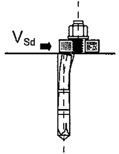
Where there are significant shear forces expected the steel bolt must also be checked for shear resistance. Steel shear failure mode is illustrated in the below diagram. This is only applicable when a shear force is present. Bolts loaded entirely in tension can skip this step. Where this verification is required the detailed calculations are shown below.
Design Verification Calculations
To ensure that the steel does not fail in shear, the shear strength of the steel provided must be greater than the shear force, as shown in the below equation;
This states that the Shear Force on Each Bolt (VEd) must be less than or equal to the Design Shear Resistance of the bolt (VRd,s) which is equal to the Characteristic Steel Shear Resistance (VRk,s) divided by the Partial Safety Factor for Steel Failure (γMs).
Shear Force on Each Bolt (VEd)
This can often be taken as the total shear force on the fixture divided by the number of bolts. For asymmetrical fittings an assessment must be done to ascertain the load on the most heavily loaded bolt.
Partial Safety Factor for Steel Failure (γMs)
This partial safety factor is calculated using the below formula which depends on the strength of the bolt. The CivilWeb Concrete Anchorage Design Spreadsheet uses info taken from ISO 898-1 shown at the bottom of this page to calculate this value automatically but this can be manually overridden for customized bolts.
Characteristic Steel Ultimate Tensile Strength (fuk)
This can be provided by the manufacturer or can be taken from the relevant standards such as Table 3 from ISO 898-1 shown at the bottom of this page.
Characteristic Steel Yield Strength (fyk)
Similarly this value can be provided by the manufacturer or can be taken from the relevant standards such as Table 3 from ISO 898-1 shown at the bottom of this page.
Characteristic Steel Shear Resistance (VRk,s) – No Lever Arm
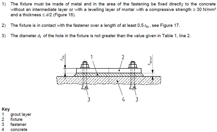
The Characteristic Steel Shear Resistance is calculated differently depending on whether a lever arm is present or not. A lever arm is not present if all the following conditions are met;
Where there is no lever arm, the Characteristic Steel Shear Resistance is calculated with the below equation;
Bolt Shear Area (As)
This is the same as is given in the tensile strength section above. This can be calculated from the diameter and thread depth of the bolt, or can be taken from standard tables such as from ISO 898-1 shown at the bottom of this page. The CivilWeb Concrete Anchorage Design Spreadsheet uses info taken from ISO 898-1 to calculate this value automatically but this can be manually overridden for customized bolts.
Characteristic Steel Ultimate Tensile Strength (fuk)
This can be provided by the manufacturer or can be taken from the relevant standards such as Table 3 from ISO 898-1 shown at the bottom of this page.
Characteristic Steel Shear Resistance (VRk,s) – Lever Arm
Where the above described conditions are not met there is a lever arm. In this case the Characteristic Steel Shear Resistance is calculated with the below equation;
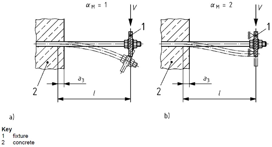
Degree of Restraint (αM)
The degree of restraint depends on the restraint of the fastening at the side of the fixture. This is equal to 1.0 when the fixture can rotate freely, and is equal to 2.0 when the fixture cannot rotate. This can only be assumed when the fixture is clamped to the fastening by a nut and washer which prevents any rotation. Where there is any doubt, this should be taken as 1.0.
Examples of restraint conditions are given in the below diagram.
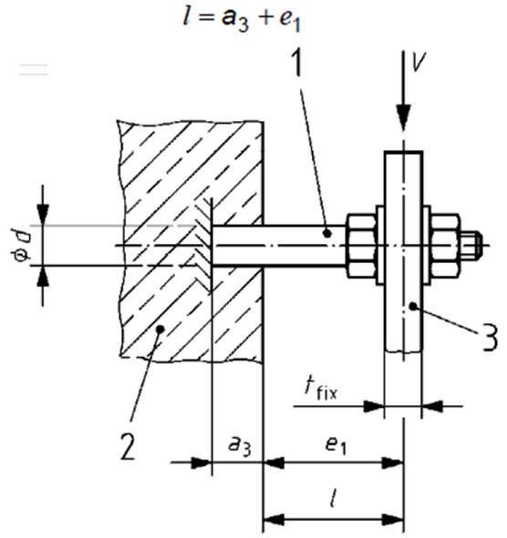
Lever Arm Length (l)
The lever arm length (l) can be determined from the below equation;
(a3)
This is taken as half of the bolt thread diameter. Shown in the below diagram.
(e1)
Distance between the shear load and the concrete surface, as shown below.
Bending Resistance (MRk,s)
The bending resistance of the anchor is calculated from the below equations.
Elastic Section Modulus (Wel)
This is calculated from the bolt radius (r) using the below equation;
Characteristic Steel Ultimate Tensile Strength (fuk)
As described above. This can be provided by the manufacturer or can be taken from the relevant standards such as Table 3 from ISO 898-1 shown at the bottom of this page.
Characteristic Steel Bending Resistance (NRk,s)
This is a multiple of the cross sectional area of the bolt (As) and the bolt tensile strength (RM).
Bolt Shear Area (As)
This is the same as is given in the tensile strength section above. This can be calculated from the diameter and thread depth of the bolt, or can be taken from standard tables such as from ISO 898-1. The CivilWeb Concrete Anchorage Design Spreadsheet uses info taken from ISO 898-1 but this can be manually overridden for customized bolts.
Bolt Strength (RM)
The strength of the bolt can be taken from the manufacturer or from applicable national standards, such as ISO 898-1 shown at the bottom of this page. The CivilWeb Concrete Anchorage Design Spreadsheet uses info taken from ISO 898-1 but this can be manually overridden for customized bolts.
Partial Safety Factor for Steel Failure (γMs)
This partial safety factor is calculated using the below formula which depends on the strength of the bolt. This is calculated as above.
Tensile Force on Each Bolt (NSd)
As calculated in tensile section (NEd). This can often be taken as the total tensile force on the fixture divided by the number of bolts. For asymmetrical fittings an assessment must be done to ascertain the load on the most heavily loaded bolt.
Steel Bolt Failure – Combined Tension and Shear
Where the bolt is subject to significant tensile and shear forces, a verification check must be done on the effects of the combined loading.
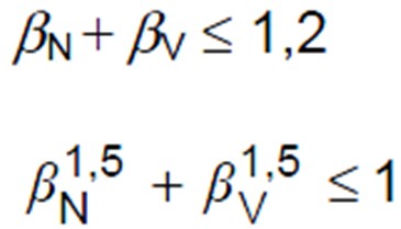
The allowances for combined loading are different depending on whether steel failure is critical or not. Where steel failure is critical the following condition must be met;
Factor of Safety (Tension) (bN)
This is the ratio of the Design Tensile Resistance of the bolt (NRd,s) and the Tensile Force on Each Bolt (NEd).
Factor of Safety (Shear) (bV)
This is the ratio of the Design Shear Resistance of the bolt (VRd,s) and the Shear Force on Each Bolt (VEd).
Where steel failure is not considered critical, either one of the below conditions must be met;
Bolt Failure
The CivilWeb Concrete Anchorage Design Spreadsheet completes all the above calculations in accordance with BS EN 1992-4. As you can see the process can be long winded and time consuming, especially for bolts subject to both tension and shear forces. This makes the completion of these calculations by hand very inefficient. The CivilWeb Concrete Anchorage Design Spreadsheet makes completing these detailed calculations easy and a fully compliant design can be completed in a matter of minutes.
Get your copy of the CivilWeb Concrete Anchorage Design Spreadsheet now for only £20.
Download Free Trial Version
To try out a fully functional free trail version of this software, please Click Here or enter your email address below to sign up to our newsletter.
