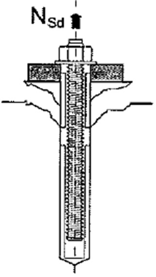
Combined concrete cone failure and anchor bolt pullout failure occurs when the bond between the grout or resin bonding agent and the concrete fails allowing the bolt and grout or resin to pull out from the concrete, taking a small cone of concrete as well. This failure mechanism is illustrated in the diagram below.
This failure mode is applicable only to chemically bonded anchors. The CivilWeb Concrete Anchorage Design Spreadsheet completes the calculations detailed below for chemically bonded anchors in accordance with BS EN 1992-4.
Design Verification Calculations
To avoid this failure mode the bond strength of the bonding agent and the concrete plus the small concrete cone strength must be greater than the tensile pullout force, as shown in the below equation.
Partial Safety Factor for Combined Cone and Bolt Pull Out Failure (γMp)
This partial safety factor is calculated using the below formula which depends on the quality of the installation.
Partial Safety Factor for Concrete (γc)
A value of 1.5 is typically recommended.
Characteristic Resistance to Combined Concrete Cone and Anchor Bolt Pullout Failure (NRk,p)
This is given by the following equation;
Initial Characteristic Resistance to Combined Cone and Pull-Out Failure (NRk,p0)
The initial value is given by the following equation;
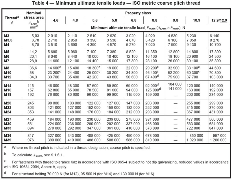
Bolt Diameter (d) (mm)
This is the bolt diameter and can be taken from the manufacturer’s info. Standard bolt sizes are given in the tables at the bottom of this page.
Characteristic Bond Strength (τRk) (N/mm2)
This is the bond resistance achieved between the chemical anchor and the concrete surface. This can be taken from the manufacturer’s info. This can also depend on the strength of the concrete and whether the concrete is cracked or uncracked.
Effective Depth (hef)
This is the effective depth of the anchor.
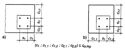
Where a narrow concrete member is being considered there may be 3 or 4 sides which are constrained by the proximity of the edges. In these cases the Effective Depth (hef) should be modified using the larger value from the following two equations;
Max Distance from Fastener Centre to Concrete Edge (Cmax)
Max Centre to Centre Spacing of Fasteners (Smax)
An example diagram is shown below.
Geometric Effects Factor (Ap,N & A0p,N)
The overall combined pullout capacity of a fastener or group of fasteners can be affected by the proximity of the concrete edges and by the capacity of other fasteners connected into a group. This is similar to the calculation for concrete cone failure but is slightly different as the cone in the combined case is smaller.
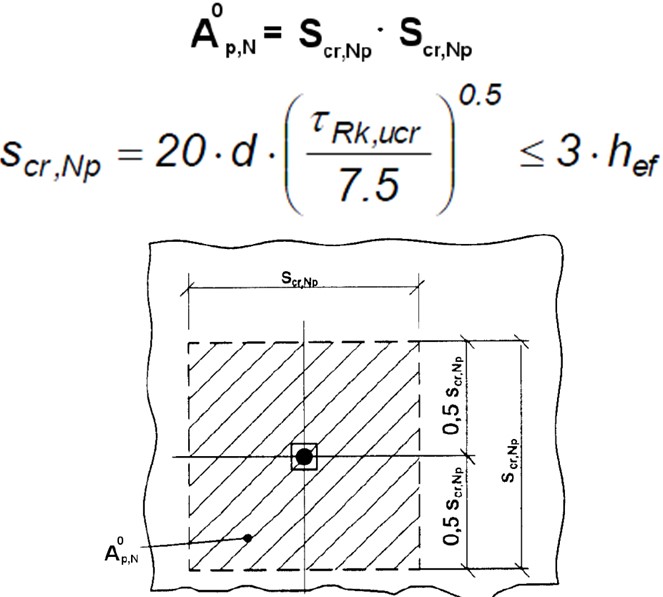
Reference Projected Area (A0p,N)
This is the idealized projected area for a single fastener unconfined by concrete edges. This can be calculated with the following equations;
Characteristic Bond Strength – Uncracked Concrete (τRk,ucr) (N/mm2)
This is the bond strength achieved in uncracked C20/25 concrete. This can be taken from the manufacturer’s info.
Effective Depth (hef)
This is the effective depth of the anchor.
Bolt Diameter (d) (mm)
This is the bolt diameter and can be taken from the manufacturer’s info. Standard bolt sizes are given in tables at the bottom of this page.
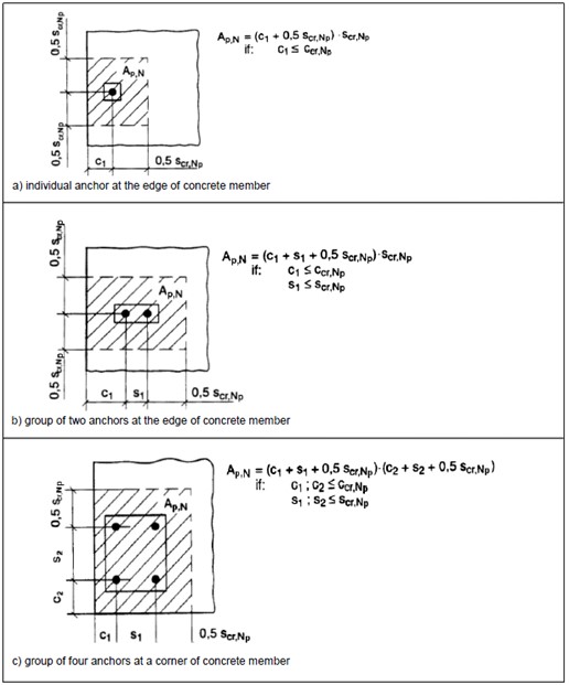
Actual Projected Area (Ap,N)
This is the idealized actual projected area for the fastener or group including confinement by concrete edges and overlapping areas of adjacent fasteners in the same group. A few examples of this calculation are shown below;
Similar to the concrete cone failure calculations described in the previous section, the calculation of these areas in practice can be laborious, particularly where the location is not fixed and needs to be optimized. The CivilWeb Concrete Anchorage Design Spreadsheet allows the user to input the basic geometrical parameters of the concrete member and the fastener or group and then calculates the maximum concrete cone resistance instantly. This can then be easily optimized by simply adjusting the position of the fastener or group.
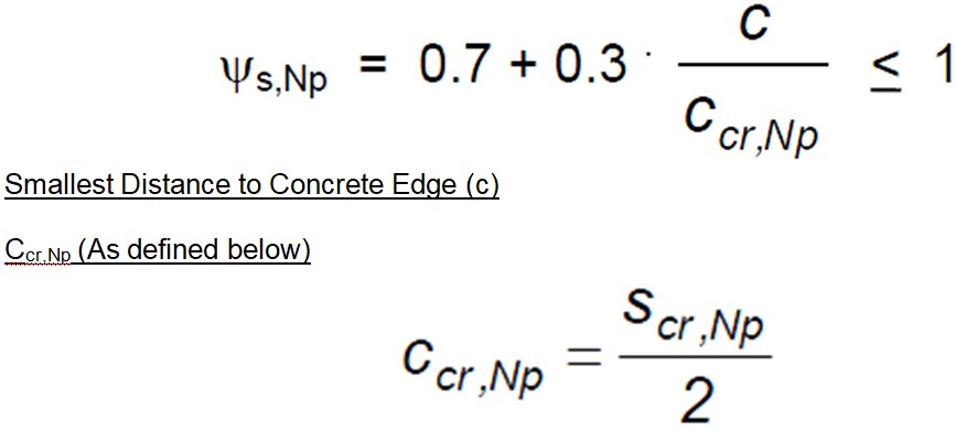
Concrete Edge Effects Factor (Ψs,N)
When a fastener or group is placed close to the edge of the concrete unit this alters the distribution of stresses in the concrete. This effect can have a significant reduction in cone pull out capacity when fasteners are installed close to the concrete edge. This effect can be calculated using the below equation;
Eccentricity Effects Factor (Ψec,Np)
This factor takes account of the effects of eccentrically loaded anchor groups. This can be calculated using the below equation;
Eccentricity of the Resulting Tensile Load (eN)
Scr,Np (As defined above)
Where the resulting tensile load is eccentric in two directions, the factor should be calculated in each direction and multiplied together.
Shell Spalling Effects Factor (Ψre,N)
For anchors installed with an Effective Depth of less than 100mm, there may be a reduction in cone pull out capacity as the strength of the reinforcement will not be fully mobilised. This is ignored if the reinforcement is densely spaced (<150mm spacing). This effect can be calculated using the below equation;
Effective Depth (hef)
This is the effective depth of the anchor.
Failure Surface Factor (Ψg,Np)
This factor allows for the effects of the failure surface for anchor groups. It can be calculated using the below equation;
Spacing (s) (mm)
The spacing of anchors in a group. Where this varies an average can be taken.
Initial Failure Surface Factor (Ψg0,Np)
This can be calculated using the below equation;
Number of Anchors in Group (n)
Effective Depth (hef)
This is the effective depth of the anchor.
Bolt Diameter (d) (mm)
This is the bolt diameter and can be taken from the manufacturer’s info. Standard bolt sizes are given in tables at the bottom of this page.
Characteristic Bond Strength (τRk) (N/mm2)
This is the bond resistance achieved between the chemical anchor and the concrete surface. This can be taken from the manufacturer’s info. This can also depend on the strength of the concrete and whether the concrete is cracked or uncracked.
Characteristic Cube Strength of Concrete (fck,cube)
This can be taken from tests taken during the concrete pour or from design info.
Cracked Concrete Factor (k)
This factor takes into account whether the concrete is cracked or uncracked. For uncracked concrete a k value of 3.2 is recommended, for cracked concrete a value of 2.3 is recommended.
Combined Concrete Cone Failure and Anchor Bolt Pullout Failure
This failure mode can be a time consuming calculation for chemical anchor design as it depends partly on the anchor bolt pullout strength and partly on the concrete cone resistance. The CivilWeb Concrete Anchorage Design Spreadsheet completes all the above calculations instantly and allows the designer to see at a glance the sensitivities of the key design parameters by displaying the unique design graphs.
Get your copy of the CivilWeb Concrete Anchorage Design Spreadsheet now for only £20.
Download Free Trial Version
To try out a fully functional free trail version of this software, please Click Here or enter your email address below to sign up to our newsletter.
