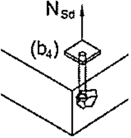
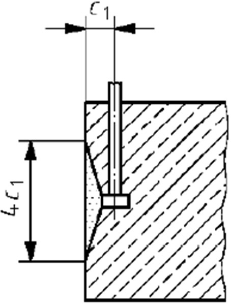
Concrete Blowout failure occurs when an anchor is installed too close to the member edge and a piece of concrete fails on the side of the member around the head of the anchor, as illustrated below. This failure mode is applicable only to Cast In anchors.
The CivilWeb Concrete Anchorage Design Spreadsheet calculates all the below calculations for cast in anchors in accordance with BS EN 1992-4.
Concrete Blowout Failure Analysis Not Required
Concrete blowout failure only occurs when a cast in anchor is installed close to the edge of a member. For this reason a detailed analysis is not required if the edge distance in all directions is greater than 0.5 . hef.
Where analysis is required, the Concrete Blowout Resistance (NRd,cb) must be greater than or equal to the tensile force, as calculated in the below equations;
Partial Safety Factor for Concrete Blowout Failure (γMc)
This is the partial factor of safety applied to concrete failure. A value of 1.5 is typically recommended.
Characteristic Resistance to Blowout Failure (NRk,cb)
This is calculated using the below equations;
Get your copy of the CivilWeb Concrete Anchorage Design Spreadsheet now for only £20.
Edge Distance (C1)
This is the distance from the center of the anchor to the nearest member edge, as defined in the diagram below.
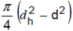
Head Load Bearing Area (Ah)
This can be calculated from the dimensions of the head and bolt.
Characteristic Cube Strength of Concrete (fck,cube)
This can be taken from tests taken during the concrete pour or from design info.
Geometric Effects of Axial Spacing and Edge Distance (Ac,Nb & Ac0,Nb)
This effect takes into account the effects of the anchor spacing and the distance to the member edge.
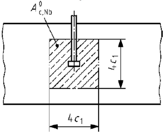
Reference Projected Area (Ac0,Nb)
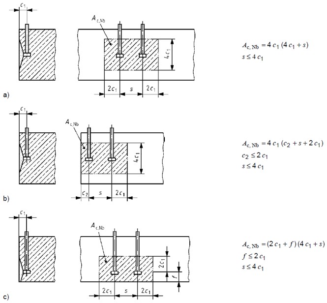
This is the standard projected area created by a single anchor at distance c1 from the member edge. This is shown in the below diagram.
Actual Projected Area (Ac,Nb)
This is the actual projected area created by the anchor or group of anchors at distance c from the member edge. This can be limited by the member depth and by the overlapping areas from adjacent anchors. Examples of this calculation are shown below.
Concrete Edge Effects Factor (Ψs,Nb)
When a fastener or group is placed close to a corner edge of the concrete unit this alters the distribution of stresses in the concrete. This effect can have a significant reduction in blowout resistance capacity when fasteners are installed close to the concrete corner. This effect can be calculated using the below equation;
Edge Distance (C1)
This is the distance from the centre of the anchor to the nearest edge.
Second Edge Distance (C2)
This is the distance from the centre of the anchor to a second member edge.
Bearing Area Factor (Ψg,Nb)
This factor allows for the effects of the individual fasteners within anchor groups. It can be calculated using the below equation;
Spacing (s1) (mm)
The spacing of anchors in a group. Also;
Number of Anchors (n)
This is the number of anchors in a row parallel to the concrete edge.
Edge Distance (C1)
This is the distance from the centre of the anchor to the nearest edge.
Eccentricity Effects Factor (Ψec,Nb)
This factor takes account of the effects of eccentrically loaded anchor groups. This can be calculated using the below equation;
Eccentricity of the Resulting Tensile Load (eN)
Edge Distance (C1)
This is the distance from the centre of the anchor to the nearest edge.
Positional Effects Factor (Ψucr,N)
This factor takes into account the position of the fastening in cracked or uncracked concrete. For uncracked concrete Ψucr,N = 1.4, for cracked concrete Ψucr,N = 1.0. The definition of cracked and uncracked concrete is given in Appendix B.
Concrete Blowout Failure
Concrete blowout failure is not commonly a critical factor but can be for cast in anchors installed close to the edge of a member. In these cases this design check must be completed. The CivilWeb Concrete Anchorage Design Spreadsheet completes the concrete blowout design procedure detailed above in accordance with BS EN 1992-4 and includes unique design features making the process quick and easy for the designer.
Download Free Trial Version
To try out a fully functional free trail version of this software, please Click Here or enter your email address below to sign up to our newsletter.
Initial Characteristic Resistance to Blowout Failure (NRk0,cb)
This is calculated using the below equations;
