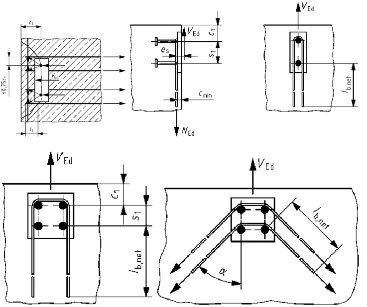
Supplementary reinforcement is often used for cast in anchors. In some cases where cast in anchors are required to resist heavy loads or are required to be installed close to the edge of concrete members, supplementary reinforcement can be provided to strengthen the member. This means that the concrete cone failure calculations can be ignored and the following calculations used instead. This supplementary reinforcement typically consists of steel reinforcement bars installed parallel with the anchors to resist the tensile force acting on the anchor. A typical arrangement is shown below. The CivilWeb Concrete Anchorage Design Spreadsheet is able to complete all the below calculations for tensile, shear or both in accordance with BS EN 1992-4.
Supplementary Reinforcement Detailing
Where supplementary reinforcement is required it should be designed in accordance with the following requirements;
- The reinforcement should consist of ribbed reinforcing bars with a yield tensile strength not greater than 500N/mm2.
- The bars should not be larger than 16mm diameter (ds).
- If more than one bar is used, the bars should generally all be the same diameter (ds).
- The bars should be detailed as stirrups or loops with a mandrel diameter according to BS EN 1992-1-1.
- The reinforcement should be placed as close as possible to the anchors to minimise the eccentricity effect associated with the angle of the concrete cone failure.
- The reinforcement must not be further away than 0.75 times the effective depth (hef).
- Where possible the supplementary reinforcement should enclose the surface reinforcement.
- The minimum anchorage length of supplementary reinforcement in the assumed concrete failure cone is 4 times the reinforcement diameter (ds) for anchorage with bends, hooks or loops, or 10 times the reinforcement diameter (ds) for anchorage with straight bars with or without welded transverse bars.
- Surface reinforcement should also be provided as shown in the above diagram sufficient to resist the forces arising from the strut and tie model. This should also take into account the concrete splitting forces as calculated in the concrete splitting failure section.
Supplementary Reinforcement Design Checks Required
If supplementary reinforcement is required it should be designed to provide the tensile capacity required, as per the below equation;
Required Tensile Capacity of Supplementary Reinforcement (NEd,re)
The design tensile forces acting on the supplementary reinforcement can be calculated using an appropriate strut and tie model, as per the above diagram. Where required, the supplementary reinforcement should be designed to resist the total tensile load on the anchor.
Characteristic Supplementary Reinforcement Tensile Resistance (NRk,re)
The characteristic supplementary reinforcement tensile resistance can be calculated using the following equation;
Cross Sectional Area of Each Leg (As)
This is the cross sectional area of each effective leg of the supplementary reinforcement.
Nominal Yield Strength of the Reinforcing Steel (fyk)
This cannot be taken as more than 500 N/mm2.
Number of Legs (n)
This is the number of legs of the supplementary reinforcement which are considered effective as per the requirements detailed above.
Partial Safety Factor for Steel Failure (γMs, re)
This partial safety factor for reinforcing steel is typically taken as 1.15 in the UK.
Supplementary Reinforcement Steel Failure (Shear)
Supplementary reinforcement can also be used for cast in anchors loaded in shear. This can consist of either surface reinforcement or additional stirrups or loops as shown in the below diagrams.
Supplementary Reinforcement for Shear - Detailing
Where supplementary reinforcement for shear forces is required it should be designed in accordance with the following requirements;
- The reinforcement should consist of ribbed reinforcing bars with a yield tensile strength not greater than 500N/mm2.
- The bars should not be larger than 16mm diameter (ds).
- If more than one bar is used, the bars should generally all be the same diameter (ds).
- The mandrel diameter should comply with BS EN 1992-1-1.
- Where surface reinforcement is used, the reinforcement must not be further away than 0.75 times the distance to closest concrete edge (C1).
- Where possible the supplementary reinforcement should enclose the surface reinforcement.
- Where surface reinforcement is used the minimum anchorage length of supplementary reinforcement in the assumed concrete failure cone is 4 times the reinforcement diameter (ds) for anchorage with bends, hooks or loops, or 10 times the reinforcement diameter (ds) for anchorage with straight bars with or without welded transverse bars.
- Reinforcement along the edge of the member should also be provided as shown in the above diagram sufficient to resist the forces arising from the strut and tie model. A simplified compression strut angle of 45° can be assumed.
Supplementary Reinforcement for Shear - Design Checks Required
If supplementary reinforcement for shear is required it should be designed to provide the capacity required, as per the below equation;
Partial Safety Factor for Steel Failure (γMs, re)
This partial safety factor for reinforcing steel is typically taken as 1.15 in the UK.
Design Supplementary Reinforcement Tensile Capacity (VEd, re)
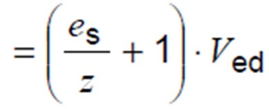
The tension forces produced in the supplementary reinforcement as a result of the shear forces acting on the fixture can be calculated using the following equations;
Design Shear Force (Ved)
This is the total design shear force acting on the fixture.
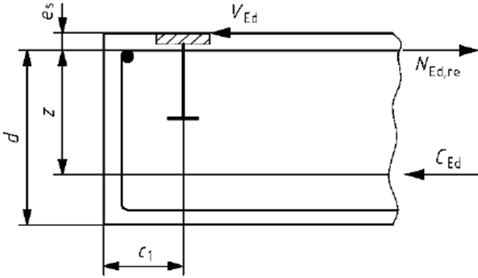
Distance Between Reinforcement and Shear Force (es)
This is shown in the below diagram.
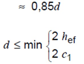
Internal Lever Arm of Concrete Member (z)
This can generally be calculated with the below equations;
Effective Depth (hef)
This is the effective depth of the anchor.
Distance from Concrete Edge (c1)
This is shown in the above diagram.
Characteristic Supplementary Reinforcement Tensile Resistance (VRk,re)
The characteristic supplementary reinforcement tensile resistance can be calculated using the following equation;
Efficiency Factor (k6)
This factor takes account of the efficiency of the type of supplementary reinforcement provided. For surface reinforcement a value of 1.0 is recommended, for stirrups or loops a value of 0.5 is recommended.
Cross Sectional Area of Each Leg (As)
This is the cross sectional area of each effective leg of the supplementary reinforcement.
Nominal Yield Strength of the Reinforcing Steel (fyk)
This cannot be taken as more than 500 N/mm2.
Number of Legs (n)
This is the number of legs of the supplementary reinforcement which are considered effective as per the requirements detailed above.
Supplementary Reinforcement Anchorage Failure (Tension or Shear)
Supplementary reinforcement used to resist either tensile or shear forces must be suitable anchored into the assumed concrete cone failure zone.
Design Checks Required
Supplementary reinforcement designed to resist shear forces on the anchor need not be assessed for anchorage in the failure zone if they are designed as loops or stirrups as detailed in the previous section. All tensile supplementary reinforcement and surface supplementary reinforcement for shear must be assessed to ensure that the anchorage capacity of the reinforcement is greater than the tensile forces to be resisted. This is shown in the below equation;
Design Anchorage Resistance (NRd, a)
This can be calculated using the following equations;
Supplementary Reinforcement Diameter (ds)
This is the diameter of the bars used as supplementary reinforcement. This should not generally be greater than 16mm.
Anchorage Length (l1)
This is the length of the reinforcement within the assumed concrete failure zone. This must be a minimum of either 4 times the reinforcement diameter (ds) for anchorage with bends, hooks or loops, or 10 times the reinforcement diameter (ds) for anchorage with straight bars with or without welded transverse bars.
Influencing Factor (α)
This factor takes into account the difference in performance between straight and hooked reinforcement. For straight bars a value of 1.0 can be used, for hooked bars a value of 0.7 is recommended.
Number of Legs (n)
This is the number of legs of the supplementary reinforcement which are considered effective as per the requirements detailed above.
Concrete Design Bond Strength (fbd)
This is the design bond strength between the concrete and the reinforcing steel. This can calculated using the below equations taken from BS EN 1992-1-1. For ribbed reinforcement bars, the concrete design bond strength can be taken as;
Bond Condition Coefficient (η1)
This factor relates to the quality of the bond condition and to the position of the bar during concreting. In normal conditions this can be taken as 1.0. Where the bond condition is unknown or for slip forms, a value of 0.7 is recommended.
Bar Diameter Coefficient (η2)
This factor relates to the bar diameter. For all bars smaller than or equal to 32mm this can be taken as 1.0. Otherwise the below equation is used;
Supplementary reinforcement bars should not be greater than 16mm diameter, so this value should always be 1.0.
Design Concrete Tensile Strength (fctd)
This can be estimated using the following equation taken from BS EN 1992-1-1;
Long Term Coefficient (αct)
This factor takes account of the long term factors which affect the tensile strength of concrete. A value of 1.0 is recommended in the UK National Annex.
Partial Safety Factor for Concrete (γc)
This is the partial factor of safety applied to concrete failure. A value of 1.5 is typically recommended.
Characteristic Axial Tensile Strength, 5% Fractile (fctk, 0,05)
This value is a lower bound estimate of the tensile strength of the concrete. Typical values relating to the concrete compressive strength are shown below. Note that this value should typically be limited to the value for C60/75 concrete due to the increasing brittleness of high strength concrete.
Supplementary Reinforcement - CivilWeb Concrete Anchorage Design Spreadsheet
The CivilWeb Concrete Anchorage Design Spreadsheet is able to compete all the above caluclations for tension, shear or both in accordance with BS EN 1992-4. Unique design features including the design graphs allow the designer to optimize the supplementary reinforcement design in minutes.
Get your copy of the CivilWeb Concrete Anchorage Design Spreadsheet now for only £20.
Download Free Trial Version
To try out a fully functional free trail version of this software, please Click Here or enter your email address below to sign up to our newsletter.


