Generally it is highly recommended that an infiltration test is undertaken before detailed design of a soakaway is completed. However it is sometimes useful to calculate a design infiltration rate from geotechnical principles. This may be useful at preliminary or feasibility stage, or if onsite testing is limited or impossible. In some countries such as the US, calculations such as those shown in this section are routinely used in place of onsite testing.
The infiltration rate of water through saturated soils is a common problem and can be solved directly through Darcy’s Law. Flow from a soakaway pit however should be through unsaturated layers as the base of the soakaway should always be above the groundwater level. The equations governing unsaturated flow are more complex non-linear differential equations which are impractical to solve directly in this case.
There is however an empirical solution which has been proposed to turn theoretically correct values for saturated flow into unsaturated flow useful for soakaway design. The proposed design procedure as used in some of the states of the US is detailed below;
- First the saturated hydraulic conductivity of the underlying soils must be ascertained using one of the below methods;
- This can be done by taking samples and measuring the saturated hydraulic conductivity in the laboratory using either the constant head or falling head permeability test.
- Alternatively there are a number of field tests which can estimate the saturated hydraulic conductivity value.
- Where existing site investigation data must be used the saturated hydraulic conductivity can be determined from soil grading information using the below empirical relationship;
- As a starting point for preliminary designs some typical values for saturated hydraulic conductivity are given below;
| Soil Type | Ksat (cm/h) | Ksat (m/s) |
| Sand | 21.00 | 5.83E-01 |
| Loamy Sand | 6.11 | 1.70E-01 |
| Sandy Loam | 2.59 | 7.19E-02 |
| Loam | 1.32 | 3.67E-02 |
| Silt Loam | 0.68 | 1.89E-02 |
| Sandy Clay Loam | 0.43 | 1.19E-02 |
| Clay Loam | 0.23 | 6.39E-03 |
| Silty Clay Loam | 0.15 | 4.17E-03 |
| Sandy Clay | 0.12 | 3.33E-03 |
| Silty Clay | 0.09 | 2.50E-03 |
| Clay | 0.06 | 1.67E-03 |
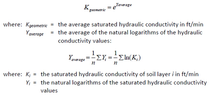
- Next the geometric mean saturated hydraulic conductivity of the soils must be determined. This is done using the below equation (note the units);
- Finally the design infiltration rate can be determined using the below empirical relationships (note the units);
Infiltration Trenches
For infiltration trenches the procedure is slightly different;
- The saturated hydraulic conductivity of the underlying soils is ascertained in the same way as the soakaway above.
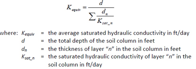
- The effective average saturatic hydraulic conductivity is then calculated in a slightly different manner using the equation below;
- Next the hydraulic gradient must be calculated, using the below equation;
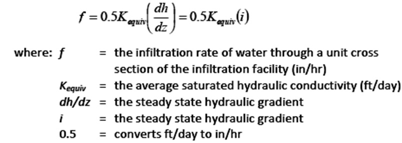
- The theoretical infiltration rate can now be calculated using Darcy’s Law;
- And finally a reduction factor is applied to take account of long term siltation effects. The US standard uses the below table, though this could be assessed in a similar manner to the UK Factor of Safety.
Related Spreadsheets from CivilWeb;
Soakaway Design Spreadsheet
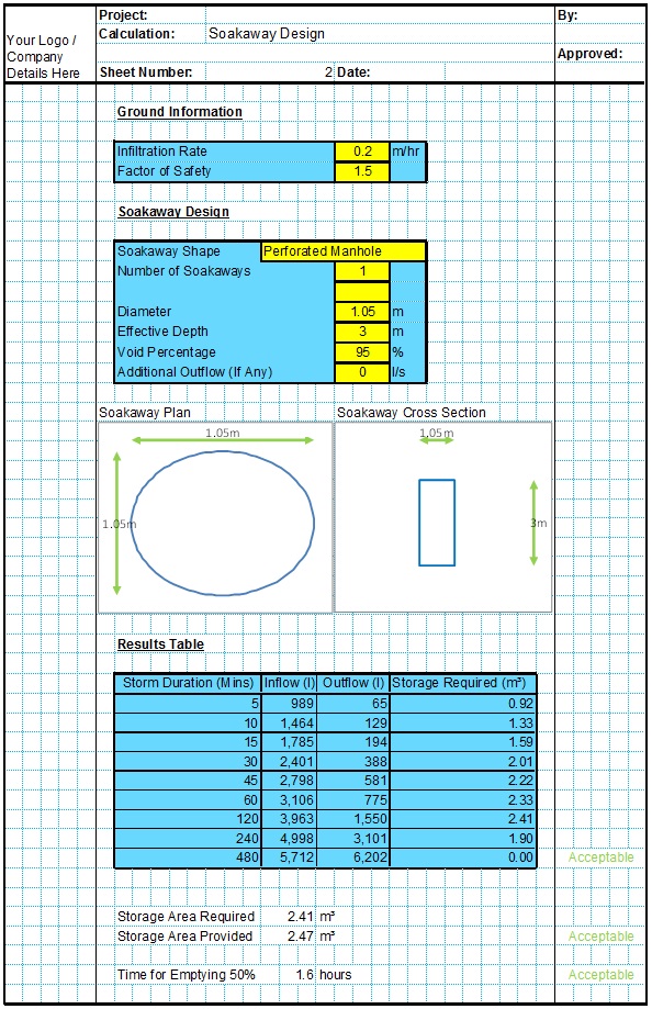
This spreadsheet calculates the requirements for a soakaway system and assists the user to design a suitable system.
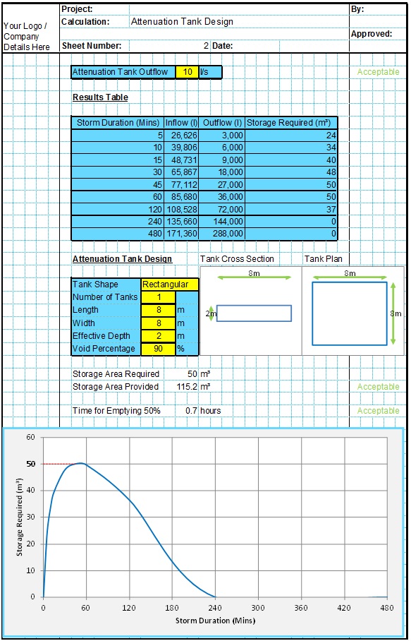
Attenuation Design Spreadsheet
This spreadsheet calculates the requirements for a attenuation system and assists the user to design a suitable system.
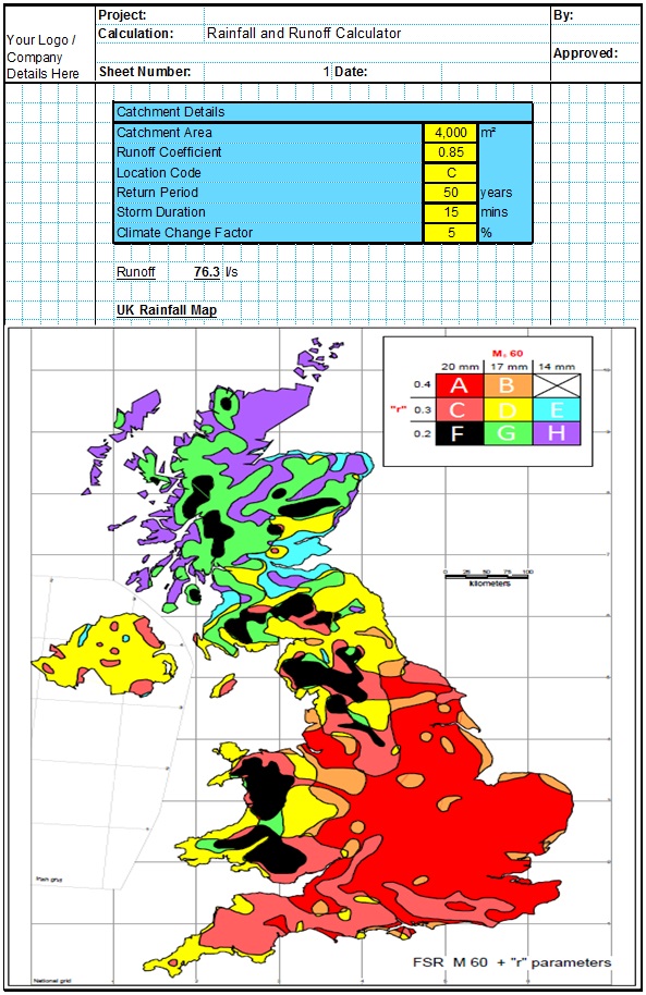
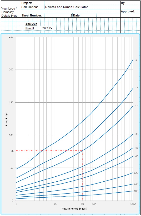
Runoff Calculator Spreadsheet
This spreadsheet calculates the design runoff flow for a site in accordance with the a number of different methods including the Wallingford Procedure.
Full Drainage Design Suite
Full drainage design suite (50% Discount) including 7 spreadsheets;
- Colebrook White Pipe Design
- Manning Pipe Design
- Manning Open Channel Design
- Linear Drainage Design
- Runoff Calculator
- Attenuation Design
- Soakaway Design

