Soakaway pit design can be a fairly complex task, particularly when there are restrictions on the size or depth of the soakaway and the details must be optimized. A software package such as the CivilWeb Soakaway Design Spreadsheet can assist with the soakaway pit design calculations and is essential if an optimal design is required.
The CivilWeb Soakaway Design Spreadsheet also comes complete with a 125 page Ultimate Soakaway Design Guide which includes all the information you need to design either large commercial soakaway systems or small garden or driveway soakaways. A simple design procedure for domestic soakaways using the CivilWeb Soakaway Design Spreadsheet and Design Guide which can be followed by anyone is included here.
Alternatively you can use our Soakaway Design Service. We can offer bespoke soakaway designs completed in accordance with BRE 365, delivered in just 2 working days.
Soakaway Pit Design
A Soakaway is a pit or trench where surface water is allowed to collect and slowly soak into the surrounding soil or rock. They are also referred to as dry wells, soak wells or soak pits in other countries, but in the UK are known as soakaways. Detailed design guidance is given in BRE Digest 365 or CIRIA Report C753.
Soakaways typically consist of one of the following constructions;
- Soakaway Pit with Perforated Manhole – Precast manhole rings can be purchased with holes in them to allow water to percolate through the manhole ring and into the surrounding soils.
- Rectangular Soakaway Pit – Simply an excavated pit where the water is stored. The pit can be filled with hardcore or left open depending on the amount of storage required or the space available. The pit can either be lined or unlined depending on the characteristics of the surrounding soils.
- Soakaway Crates – Specially made modular plastic crates which can be combined to produce a storage area for water. These can be installed beneath new surfacing as part of a SUDS system.
- Trench Soakaway – A trench where water can be stored. Similar to a long rectangular pit, an infiltration trench can be filled or unfilled, lined or unlined depending on the circumstances. Generally provides a larger surface area than a pit.
- Borehole Soakaway- Specialist type of soakaway where a borehole is installed to allow water to infiltrate into deeper soil layers, while the water is stored close to the surface.
Soakaway Design Considerations
The following conditions should be considered before any soakaway system is designed;
- Ground conditions should be suitable for a rainwater soakaway. The ground water level should be below the proposed base. The ground should not be contaminated and ground slopes and other sources of instability may need to be considered.
- The ground should be suitable for infiltration. The infiltration rate through the ground needs to be sufficient for the water to soak into the ground in a few days. A percolation test will usually be required to ascertain the infiltration rate before detailed soakaway pit designs are finalised. In some cases a soil hydraulic conductivity analysis may also be justified.
- Soakaways constructed in clay soils sometimes require further considerations.
- Soakaways must be constructed a suitable distance away from houses, buildings, roads and other potentially sensitive structures.
- The water quality of the runoff must be considered and checked that it is suitable for infiltration through a soakaway.
- Any amenity and biodiversity benefits of a soakaway should be considered and evaluated in comparison with any alternative solutions.
- The whole life costs of the soakaway should be considered and compared with alternative solutions.
- If an existing soakaway is to be utilised as part of the scheme a soakaway test should be conducted to ascertain the performance of the soakaway before detailed design is completed.
Detailed Soakaway Pit Design
A general procedure for detailed soakaway pit design is given below;
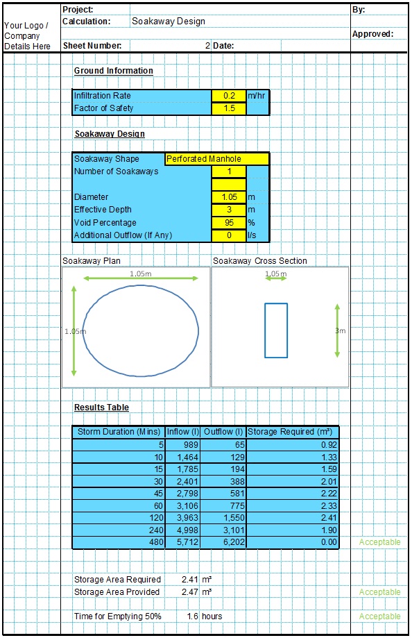
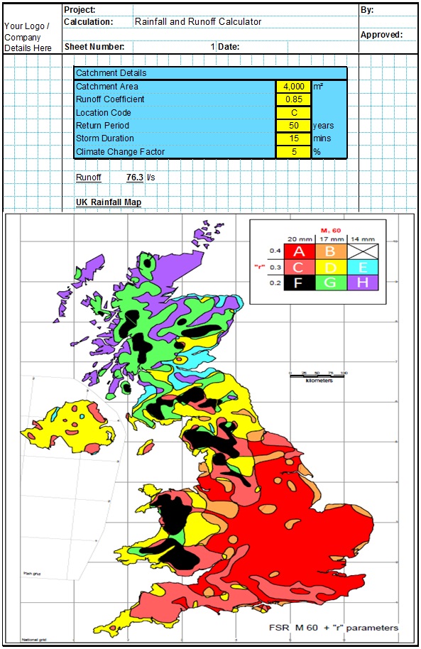
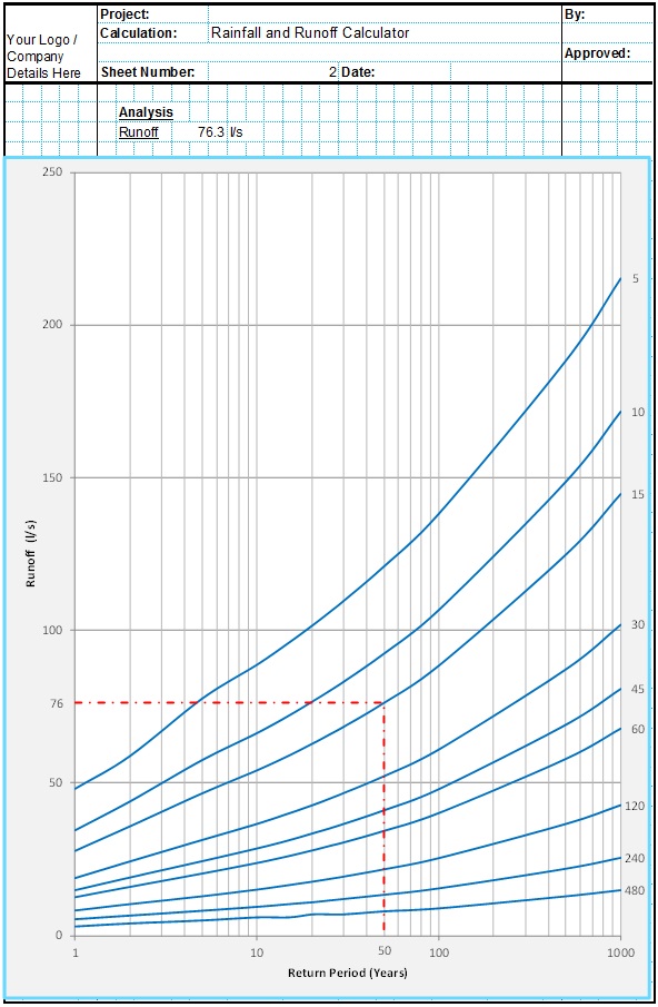
- Firstly the rainfall and runoff characteristics of the catchment served by the soakaway need to be ascertained. The CivilWeb Soakaway Design Spreadsheet allows the user to analyse rainfall and runoff characteristics in accordance with the Wallingford Procedure, which is suitable for most developments in the UK. The user inputs the catchment area, runoff coefficient, design return period, climate change allowance and location and the spreadsheet calculates the runoff characteristics for all possible design storm events.
- Next the infiltration rate is entered. This should usually be taken from a percolation test conducted in accordance with the procedure outlined in BRE Digest 365. Also an infiltration factor of safety can be specified.
- Next the soakaway details are entered. This includes the soakaway type, size and depth of the soakaway and the porosity of any backfill materials. The user can also specify a base infiltration factor and any additional outflows.
- The spreadsheet then plots a graph showing the water storage volume requirements for all design storm durations up to 48hrs, and how this relates to the maximum calculated water storage volume of the specified soakaway. This shows the user at a glance whether the soakaway is large enough or whether the infiltration rate needs to be improved by deepening the soakaway. The spreadsheet also calculates the time of emptying in accordance with BRE Digest 365 guidelines.
How to Build a Soakaway
Once the detailed design of the soakaway has been finalised, the soakaway can be detailed and constructed. The following factors should be considered as part of these stages;
- Soakaways should include a membrane which prevents sediments from migrating into the soakaway.
- A thorough soakaway specification should be put together, similar to the specification detailed here.
- A construction detail should be issued to the installer. Some example can be found here.
- There are a number of factors to consider to ensure that the soakaway is installed correctly. Some factors to consider are detailed here.
- It is important that sediment and oil interception methods are employed upstream of the soakaway to minimise maintenance requirements and the risks of the soakaway from becoming blocked. This can include silt fences deployed either permanently or as part of the construction phase only.
- If the soakaway is to be adopted certain design and construction requirements should be considered.
- Soakaway maintenance is likely to include some sediment waste management which should be considered at an early stage.
- Decommissioning should also be considered at this stage to ensure that there will be no unforeseen problems in the future if/when the soakaway needs to be removed.
Related Spreadsheets from CivilWeb;
Soakaway Design Spreadsheet
This spreadsheet calculates the requirements for a soakaway system and assists the user to design a suitable system.
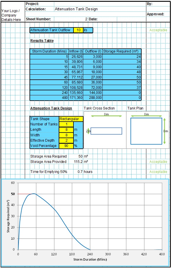
Attenuation Design Spreadsheet
This spreadsheet calculates the requirements for a attenuation system and assists the user to design a suitable system.
Runoff Calculator Spreadsheet
This spreadsheet calculates the design runoff flow for a site in accordance with the a number of different methods including the Wallingford Procedure.
Full Drainage Design Suite
Full drainage design suite (50% Discount) including 7 spreadsheets;
- Colebrook White Pipe Design
- Manning Pipe Design
- Manning Open Channel Design
- Linear Drainage Design
- Runoff Calculator
- Attenuation Design
- Soakaway Design


