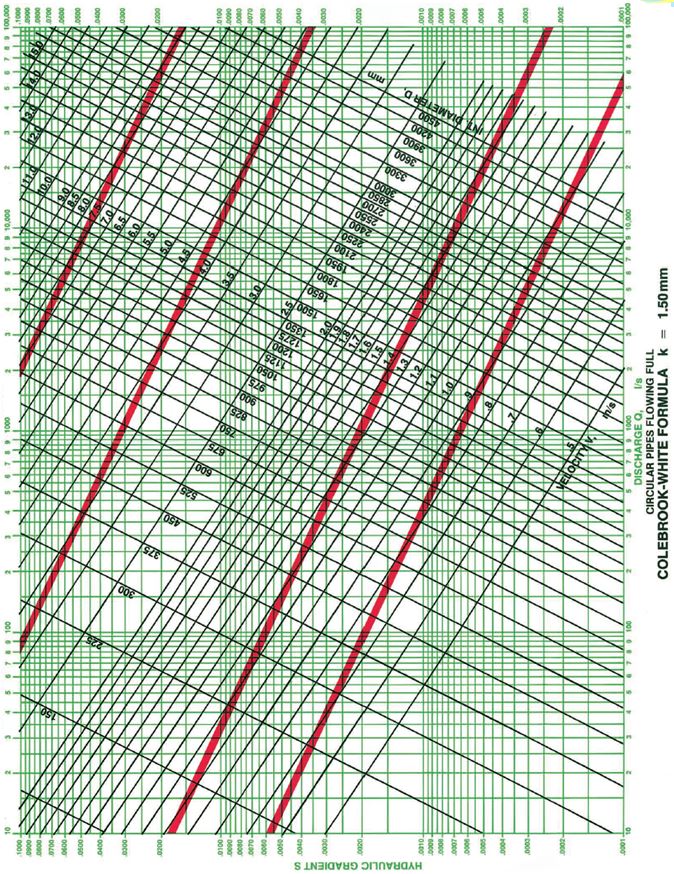
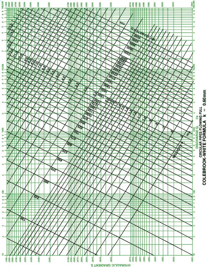
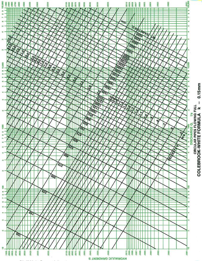
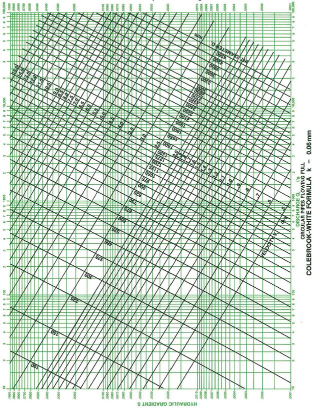
The Colebrook-White equation was developed in 1939. Colebrook conducted a number of experiments on commercially available pipes to compare theoretical pipe flow equations with pipes of non-uniform roughness as is found in practice. These experiments lead to the adoption of the roughness coefficient and in combination with the von Karman-Prandtl and Darcy-Weisbach formula produced an equation for turbulent flow for non-uniform roughness pipes. In1958 the Hydraulics Research Station published Charts for the Hydraulic Design of Channels and Pipes which greatly simplified the practical use of the equation and the Colebrook-White equation gradually became accepted as the most accurate way of predicting flow through pipes in a wide range of practical situations. Examples of these design charts are included below.
Flow in Pipes Running Full
The Colebrook White equation calculates the velocity (v) of flow through a circular pipe running full using the below equation;

Gravitational Constant (g) (m/s2)
This is the acceleration due to gravity, typically taken as 9.81m/s2 at sea level.
Internal Pipe Diameter (D)
This is the internal diameter of the pipe being considered.
Hydraulic Gradient (JE)
This is effectively the slope of pipe in m/m.
Kinematic Viscosity of Water (vk) (mm2/s)
This describes the viscosity of the liquid, water in this case. The kinematic viscosity is the absolute or dynamic viscosity divided by the liquids density at that temperature. The kinematic viscosity of water is around 1.139 at 15°C which is the value usually used for design. This value does vary depending on the temperature of the liquid but the impact on the Colebrook-White equation is minimal so this variation is usually ignored. For a particular water temperature (T), the kinematic viscosity (in m2/s) can be estimated using the below equation;

A calculator tool is included in the CivilWeb Pipe Flow Calculator spreadsheet package to estimate kinematic viscosity at different water temperatures using the above equation, or some tabulated values are shown below.
Roughness Coefficient (ks) (m)
This coefficient relates to the energy lost by the water due to the friction caused by the internal roughness of the pipe. Further details can be found here.
Flow in Partially Full Pipes
To calculate the flow in pipes which are only partially full, the Internal Pipe Diameter can be replaced with 4Rh, where Rh is the Hydraulic Radius. The Hydraulic Radius is the flow cross sectional area divided by the wetted perimeter.
A graph is shown below illustrating the flow characteristics of partially full pipes. P is the Wetted Perimeter, A is the Flow Area, Q is the Discharge, V is the Velocity and R is the Hydraulic Radius.
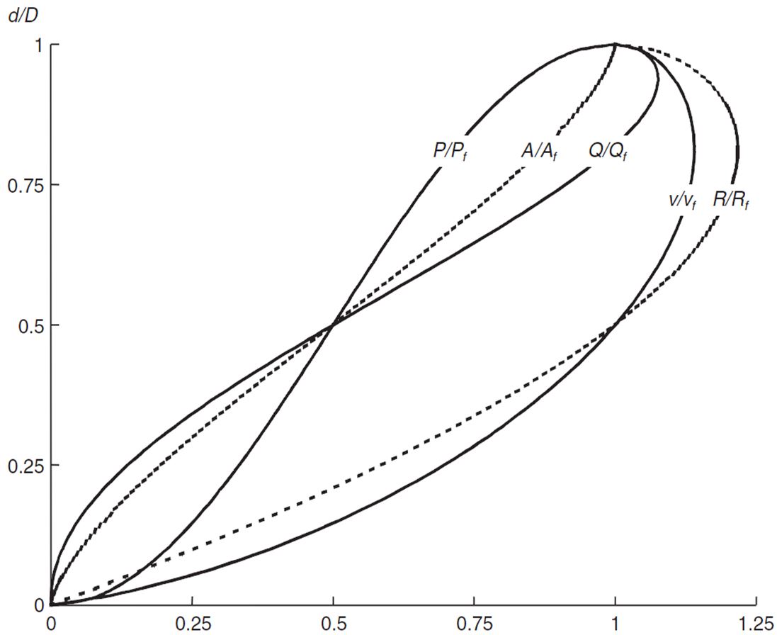
The CivilWeb Pipe Flow Calculator spreadsheet package includes a tool to analyze flow in partially full pipes. It calculates the maximum velocity and flow for the pipe being considered and allows the user to calculate specific velocities and flows for any height of water in the pipe.
Limitations
The Colebrook-White equation is not generally suitable for corrugated pipes or for pipes or channels containing significant deposits of sediment. In the past the biggest limitation with the Colebrook-White equation was its difficulty for hand calculation. This was removed when accessible charts and tables of the results were published after 1958. This is not such a problem now that calculators and computers are generally used to complete the calculations, such as the CivilWeb Pipe Flow Calculator spreadsheet package.
Another limitation of the original Colebrook-White equation is that it can only calculate the water velocity. Therefor the pipe roughness, pipe diameter and gradient must be known in advance. This makes the equation perfect for analysis of existing pipes where these factors can all be ascertained. However, it makes the design process where a flow or velocity is known and the designer wants to determine the pipe diameter and gradient. To determine any other factors using the original equation an iterative approach must be used which can be time consuming, particularly if the calculations are done by hand. The Colebrook-White charts make this process easier but cannot be relied on for precise calculations as there are always errors introduced from reading the chart.
The CivilWeb Pipe Flow Calculator spreadsheet package includes a pipe design spreadsheet which uses an accurate approximation equation developed from the Colebrook-White equation which can calculate the required pipe gradient given the diameter, velocity and pipe roughness. The design equation is shown below;

The design pipe roughness is usually known by the designer as explained above. The required water velocity is usually within a minimum and maximum, the user can specify a minimum and maximum value for design. The pipe diameter is usually a standard size as specified in the BS EN 476. Using these parameters the spreadsheet recommends suitable designs for standard pipe sizes to meet the design conditions. The spreadsheet also allows the designer to choose a pipe size and gradient based on the suggestions, then analyses the pipe flow capacity and velocity against the design conditions, highlighting any deviations. This makes the design of single drainage pipes easy with the designer able to choose a suitable pipe diameter and gradient to suit any design conditions.
A similar approximate equation also exists for determining the pipe diameter, as shown below.

Get your copy of the CivilWeb Pipe Flow Calculator spreadsheet including full Colebrook-White analysis now for only £20.
Or why not bundle the CivilWeb Pipe Flow Calculator with our Rainfall Calculator Spreadsheet for only £5 extra?
Kinematic Viscosity of Water
| Water Temperature (°C) | Kinematic Viscosity (mm²/s) |
| 2 | 1.6736 |
| 3 | 1.6191 |
| 4 | 1.5674 |
| 5 | 1.5182 |
| 6 | 1.4716 |
| 7 | 1.4272 |
| 8 | 1.3849 |
| 9 | 1.3447 |
| 10 | 1.3063 |
| 11 | 1.2696 |
| 12 | 1.2347 |
| 13 | 1.2012 |
| 14 | 1.1692 |
| 15 | 1.1386 |
| 16 | 1.1092 |
| 17 | 1.0811 |
| 18 | 1.0541 |
| 19 | 1.0282 |
| 20 | 1.0034 |
| 22 | 0.9565 |
| 24 | 0.9131 |
| 26 | 0.8729 |
| 28 | 0.8355 |
| 30 | 0.8007 |
| 35 | 0.7234 |
| 40 | 0.6579 |
| 45 | 0.6017 |
| 50 | 0.5531 |
| 55 | 0.5109 |
| 60 | 0.474 |
| 65 | 0.4415 |
| 70 | 0.4127 |
| 75 | 0.3872 |
| 80 | 0.3643 |
Related Spreadsheets from CivilWeb;
Runoff Calculator Spreadsheet
This spreadsheet calculates the design runoff flow for a site in accordance with the a number of different methods including the Wallingford Procedure.
Full Drainage Design Suite
Full drainage design suite (50% Discount) including 6 spreadsheet suites;
- Pipe Flow Calculator
- Manning Open Channel Design
- Linear Drainage Design
- Runoff Calculator
- Attenuation Design
- Soakaway Design
