Cast in anchors are those which have been installed before or during the casting of the concrete. These are the easiest, cheapest and most effective type of anchorages but obviously require detailed design at the same time as the concrete member and cannot be retrofit. The CivilWeb Concrete Anchorage Design Spreadsheet completes all the required calculations for the design of cast in anchors in accordance with BS EN 1992-4.
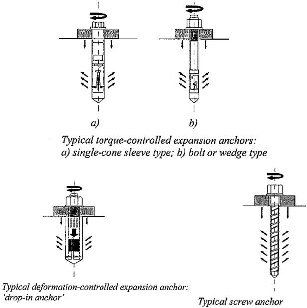
Cast in anchors usually consist of a bolt cast into the concrete member with a nut or head at the end to provide anchorage. They can also be installed with an anchor plate which increases their resistance, and sometimes have an embedded plate at the concrete surface. Some typical examples of cast in anchors are shown in the diagram below.
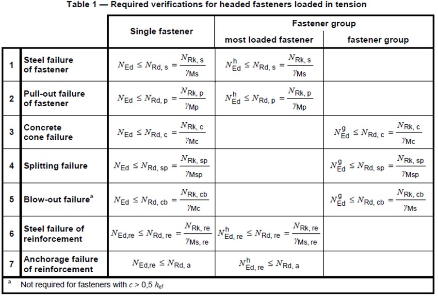
Cast in Anchors in Tension - Design Verifications Required
The following design verification checks are required for cast in anchors according to BS EN 1992-4. All these checks can be completed using the CivilWeb Concrete Anchorage Design Spreadsheet. Follow the links below for detailed explanations of how the spreadsheet calculates each design check.
- Steel Bolt Failure
- Anchor Bolt Pullout Failure
- Concrete Cone Failure
- Concrete Splitting Failure
- Concrete Blowout Failure
- Steel Reinforcement Failure
- Steel Reinforcement Anchorage Failure
These verifications are also shown in the below table.
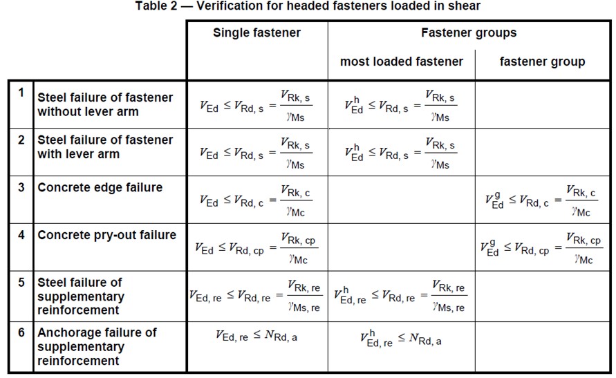
Cast in Anchors in Shear - Design Verifications Required
The following design checks are required for anchor channels under shear loading;
- Steel Bolt Failure in Shear Without Lever Arm
- Steel Bolt Failure in Shear With Lever Arm
- Concrete Edge Failure
- Concrete Pryout Failure
- Supplementary Steel Failure
- Supplementary Steel Anchorage Failure
These verifications are also shown in the below table.
Get your copy of the CivilWeb Concrete Anchorage Design Spreadsheet now for only £20.
Download Free Trial Version
To try out a fully functional free trail version of this software, please Click Here or enter your email address below to sign up to our newsletter.


