The CivilWeb Concrete Shear Wall Design Spreadsheet is a powerful spreadsheet for the design of shear walls in buildings. The spreadsheet is suitable both for the positioning of up to four different shear walls within a building and the detailed design of the shear walls themselves. The spreadsheet completes all the calculations in accordance with BS EN 1991 and BS EN 1992. The spreadsheet is simple to use and allows the designer to complete a fully compliant design of up to four shear walls in minutes. The CivilWeb Concrete Shear Wall Design Spreadsheet can be purchased at the bottom of this page for only £20.
Alternatively why not purchase our best value bundle, the full Concrete Design Suite which includes all of our reinforced concrete design spreadsheets. This is our best value design bundle and can be purchased at the bottom of this page for only £50.
Concrete Shear Wall Design
Concrete shear walls are included within buildings in order to strengthen the whole structure against lateral loads such as wind loads. A rectangular building on its own is not very strong when subjected to lateral loads. This is because a rectangular shape is not particularly strong, if the connections are not very strong the whole building can easily be deformed and damaged by lateral loadings. This is particularly the case with steel framed buildings with relatively light superstructures which cannot provide the required lateral strength from the superstructure alone.
Concrete shear walls are strong concrete walls within rectangular buildings which provide the required lateral strength. They consist of a series of strong concrete walls positioned at particular points within the building. Shear walls are usually provided in places where concrete walls can be placed without altering the layout of the building. Common examples include staircases and lift shafts. These areas are built much stronger than they would otherwise need to be in order to function as shear walls as well.
Concrete Shear Wall Design - Inputs
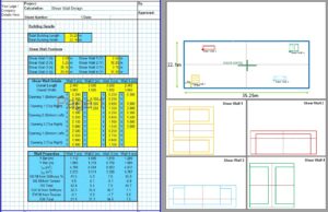
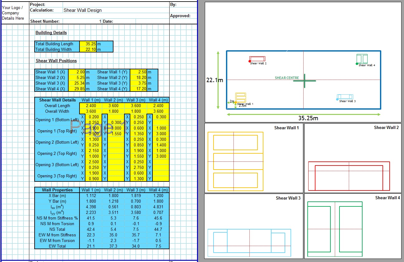
The design of concrete shear walls can be difficult to complete by hand. The CivilWeb Concrete Shear Wall Design Spreadsheet makes it easy. First the designer inputs the location of up to four shear walls within the building. The spreadsheet plots each shear wall onto a plan of the building so the designer can make sure they are positioned correctly. Then the spreadsheet calculates the shear centre and plots this on the plan. This way the designer can adjust the position of the shear walls so that the shear centre is as close as possible to the centroid of the building.
Next the designer can input the dimensions of the shear walls. This is done by specifying the size of the openings. This makes it quick and easy to get the most common shear wall shapes with minimal time spent inputting values.
The concrete shear wall design spreadsheet then calculates the design properties for each shear wall including the second moments of area in both X and Y directions, and the percentage of the lateral strength provided by each shear wall.
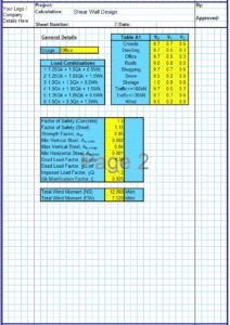
Now the designer can enter the loading conditions. This is done in accordance with BS EN 1991 and includes 6 preset load combinations. The designer must also input the maximum lateral forces expected in both X and Y directions. The RC shear wall analysis and design spreadsheet uses these forces to design the loads acting on each spreadsheet in proportion to their contribution to the structures strength in that direction.
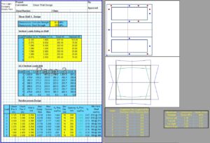
The designer can add axial loads which are also often present in shear walls. The spreadsheet plots a drawing of each concrete shear wall showing the designer exactly where the axial loads have been placed. This allows the designer to check that the axial forces have all been placed correctly on each concrete shear wall.
The RC shear wall analysis and design spreadsheet then allows the designer to analyse the reinforcement requirements for each wall in up to 8 different locations. This allows the designer to complete the design of the reinforcement for each shear wall.
The spreadsheet includes a number of handy tools which can assist the designer in completing the reinforcement design. The spreadsheet calculates the maximum tensile and maximum compressive stresses active in each part of the shear wall and plots these on a plan of the concrete shear wall. This allows the designer to see exactly where they should analyse the shear wall in order to get the critical compressive and tensile stresses for reinforcement design.
Then the spreadsheet also suggests the optimum bar size and spacing for each of the 8 load and analysis positions. This allows the designer to simply input suitable values without completing a time consuming iterative design process, testing bar sizes and spaces until they are optimised.
This procedure would be almost impossible to complete by hand in all but the most simple of cases. Using the CivilWeb Concrete Shear Wall Design Spreadsheet the designer can complete a full RC shear wall analysis and design in minutes.
CivilWeb Concrete Shear Wall Design Spreadsheet
The CivilWeb Concrete Shear Wall Design Spreadsheet is a powerful spreadsheet for the design of shear walls in accordance with BS EN 1992. The spreadsheet can include up to four different shear walls positioned anywhere within the building. The spreadsheet calculates the increase in lateral strength provided by the shear walls, then can be used to design the required reinforcement.
Buy the CivilWeb Concrete Shear Wall Design Spreadsheet now for only £20.
Or why not buy our best value bundle, the full CivilWeb RCC Design Suite which includes all of our concrete design spreadsheets for only £50, a saving of over 80%.
Download Free Trial Version
To try out a fully functional free trial version of this software, please enter your email address below to sign up to our newsletter.
