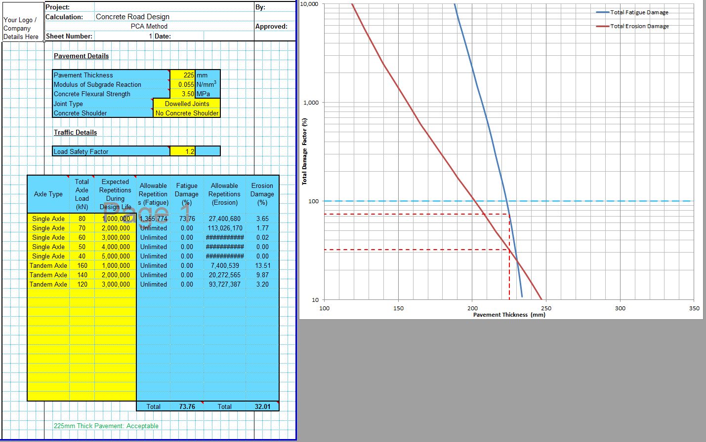
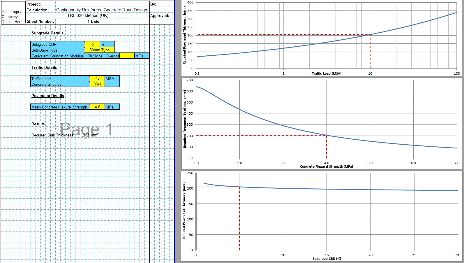
The CivilWeb PCA Pavement Design Spreadsheet completes a full concrete pavement design in accordance with the PCA method of rigid pavement design. The unique design analysis tools allows the designer to see at a glance the optimum concrete pavement thickness for the chosen loadings and whether the critical design parameter is erosion damage or fatigue damage.
The CivilWeb PCA Pavement Design Spreadsheet can be purchased further down this page for only £10. Alternatively the PCA design spreadsheet is included in the CivilWeb Rigid Pavement Design Spreadsheet Suite which includes 11 different pavement design methods along with a number of other useful design tools including concrete flexural strength calculators. Follow the above link for full details.
PCA Method of Rigid Pavement Design
The Portland Cement Association (PCA) developed a new rigid pavement design method published in 1966. This method was improved in 1984 to include a wider range of design considerations and pavement types. It included the erosion design condition and tables were included for the design of pavements with concrete shoulders and with undoweled joints.
Unlike the AASHTO rigid pavement design method which is empirically based on road test data, the PCA method was an early attempt at a mechanistic design method. The PCA method was developed based on finite element calculations of pavement stresses and deflections which were then calibrated with some simple design and performance criteria to create a series of design tables and charts. The finite element model was populated largely by Pickett’s equations based on Westergaard’s initial stress and deflection analysis.
The PCA procedure includes two main modes of pavement failure, fatigue or erosion. Fatigue failure occurs when concrete pavements fail due to the repeated damage caused by many millions of loading cycles. Erosion failure occurs when pumping or erosion of the pavement foundations leads to failure of the pavement and joint faulting. One criticism of the Westergaard method is that is does not take account of erosion type failures which were found to be very common during the AASHTO Road Test for concrete roads.
PCA Pavement Design - Fatigue Analysis
The fatigue analysis used in the PCA pavement design method is based on the edge stress condition where the load is situated on the edge of the mid-slab. This is far enough away from the slab joints for them to have a significant impact on the stresses developed in the pavement.
The edge loading condition can be reduced significantly by including a concrete shoulder. This moves the edge loading condition to an interior loading condition, significantly lowering the maximum stresses produced.
Again the PCA pavement design method omits the effects of warping and curling on the slab. This can be justified for the fatigue case as the temperature and moisture content of the slab will generally be higher at the bottom of the slab than at the top. This means that the combined warping and curling effects will have a negative net impact on the stresses produced on the slab during loading.
The PCA pavement design method accounts for the different stresses produced by loading at different distances from the edge. An analysis of typical heavy vehicle wheel load locations was undertaken to arrive at a design value of around 6% of heavy traffic occurring at the slab edge. This has an equivalent fatigue damage value of typical heavy vehicle wheel placements.
PCA Pavement Design - Erosion Analysis
The erosion analysis used in the development of the PCA pavement design method takes account of the fact that erosion failure modes are more closely related to pavement deflections than to pavement stresses. The critical condition is the slab deflection under corner loading conditions.
Erosion failure modes such as pumping and erosion of granular sub-bases was the most common form of failure for the pavements in the AASHTO Road Test. However, no satisfactory correlation with pavement deflection could be found. Correlations were found for the rate of work used to deflect the slab. This assumes that a thinner slab receives a faster rate of deflection than a thicker slab, leading to decreased durability.
PCA Pavement Design Methodology
The PCA pavement design method is detailed in the PCA publication “Thickness Design for Concrete Highway and Street Pavements”. The design methodology used by the CivilWeb PCA Pavement Design Spreadsheet is detailed below;
- The designer inputs details for a trial pavement including thickness and flexural strength. The designer is usually aiming to find an acceptable thickness for the concrete road and the thickness is also the most sensitive input as it has an exponential effect on the capacity of the pavement.
- Next the spreadsheet picks Equivalent Stress and Erosion Factor values from the tables provided in the PCA guide. Intermediate values are determined using linear interpolation.
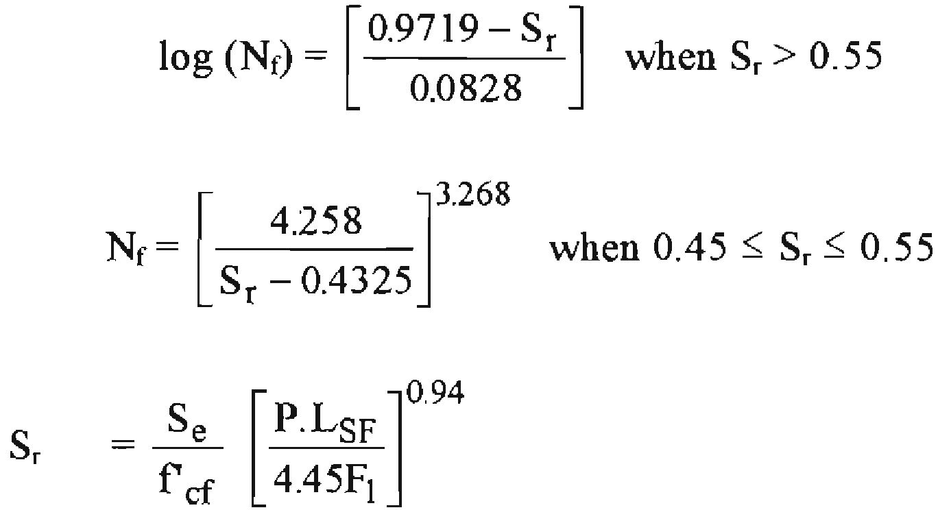
- The stress ratio factor is then used to determine the maximum allowable repetitions of a particular axle load using the below equations where Nf is the maximum allowable repetitions, Sr is the stress ratio, Se is the equivalent stress value taken from PCA tables, f’ef is the design flexural strength of the concrete, P is the total axle load, Lsf is the load safety factor and F1 is an axle type adjustment factor. These values are explained in greater detail below. The PCA guide provides a nomograph for estimating the maximum allowable load repetitions. This nomograph is reproduced in the following pages.
- The expected repetitions of the axle load during the roads design life is then divided by the maximum allowable repetitions to determine the damage factor. This is converted to a percentage by multiplying by 100.
- This procedure is repeated for all required axle loadings and the damage factors added together. If the total damage factor for all axle loads is less than 100%, the pavement is deemed to be suitable for fatigue loading.
- A similar procedure is then used to determine the erosion damage factors. The erosion factor is taken from PCA tables and then the following equation is used to determine the maximum allowable axle load repetitions where F2 is an adjustment factor to account for the presence of concrete shoulders or not and F3 is the erosion factor taken from PCA tables. Again the PCA guide includes a nomograph for estimating the maximum allowable load repetitions which is reproduced in the following pages.
- The expected axle load repetitions during the design life of the pavement is then divided by the maximum allowable load repetitions calculated above to determine the damage factor. As for the fatigue condition if the sum of all the erosion damage factors is below 100%, the pavement is deemed to be adequate.
- The CivilWeb PCA Pavement Design Spreadsheet then draws a unique design graph showing the fatigue and erosion condition damage factors for all applicable pavement thicknesses. This allows the designer to evaluate the optimum pavement thickness at a glance.
PCA Pavement Design Inputs
The inputs required to complete the PCA pavement design methodology are explained in detail in this section.
Concrete Flexural Strength
The flexural strength of the concrete is the most appropriate strength measurement to use as this most closely resembles the stresses encountered by concrete pavements supported by the ground. Pavements loaded by vehicles do encounter compressive stresses but as the compressive strength of concrete is much higher than the flexural strength, compressive strengths do not influence the design of the pavement. Further details on the flexural strength of concrete can be found in our Flexural Strength of Concrete post.
The flexural strength is therefore used to determine the stress ratio and the fatigue condition maximum allowable axle load repetitions. The PCA pavement design method basically uses a fatigue model to estimate the number of repetitions of a load the pavement can accommodate before fatigue failure. This is dependent on the ratio of loading stress and design flexural strength. A ratio below around 0.45 is not deemed to cause significant damage, whereas a higher ratio causes a lot of damage and can only be accommodated by the pavement a certain amount times before failure occurs.
The flexural strength used in the PCA pavement design method is the flexural strength measured using the third point loading test. The third point flexural strength test is considered most appropriate as this will measure the lowest flexural strength at any point in the middle third of the beam. Further details on flexural strength testing are included in our Flexural Test post.
Alternative tests such as the cantilever and centre point tests measure the flexural strength at a single point only. This will lead to higher values being measured than are achieved in practice. If an alternative flexural strength measurement is to be used it must be adjusted down to an equivalent third point load test measurement. Typically centre point tests will be around 0.5MPa higher and cantilever tests will be around 1.1MPa higher than the equivalent third point load test. Further details on flexural strength testing are included elsewhere in this document.
The PCA pavement design method also assumes that the design flexural strength is that measured after 28 days. The flexural strength of concrete continues to increase throughout the life of the pavement in a similar way to other strength parameters. This strengthening effect is included in the PCA pavement design method tables and equations and does not need to be applied by the designer. A spreadsheet tool for estimating 28 day strengths from earlier or later tests is included in our Flexural Strength of Concrete Calculator. This calculator tool can be purchased separately or is included along with the PCA pavement design spreadsheet in the CivilWeb Rigid Pavement Design Spreadsheet Suite.
The PCA pavement design method also assumes that flexural strength values achieved onsite will vary by as much as 15% compared with the design value. This represents a reasonable level of site control of flexural strength and this 15% reduction is included in the design tables and equations.
Subgrade and Subbase Support
The concrete pavement design is greatly influenced by the support given to the pavement by the underlying subgrade and any installed subbase materials. Ultimately it is these materials which resist the imposed loading on the pavement, therefore a stiffer subgrade will improve the capacity of the pavement.
The subgrade support is input very simply into the CivilWeb PCA Pavement Design Spreadsheet as a subgrade reaction modulus. The subgrade reaction modulus is the support parameter defined by Westergaard and is used as a description of the stiffness of the liquid foundation in the PCA pavement design model.
The subgrade reaction modulus of the underlying soils can be measured onsite using a plate bearing test. These tests are however quite time-consuming and expensive, so it is common to use an assumed value for the particular soil type or to apply a simple correlation with CBR values. Generally it is accepted that such correlations are sufficiently accurate to prevent any discrepancies from significantly affecting the pavement performance. It is also not generally required for summer or winter variations in the subgrade reaction modulus to be taken into account. A reasonable average value will be sufficient.
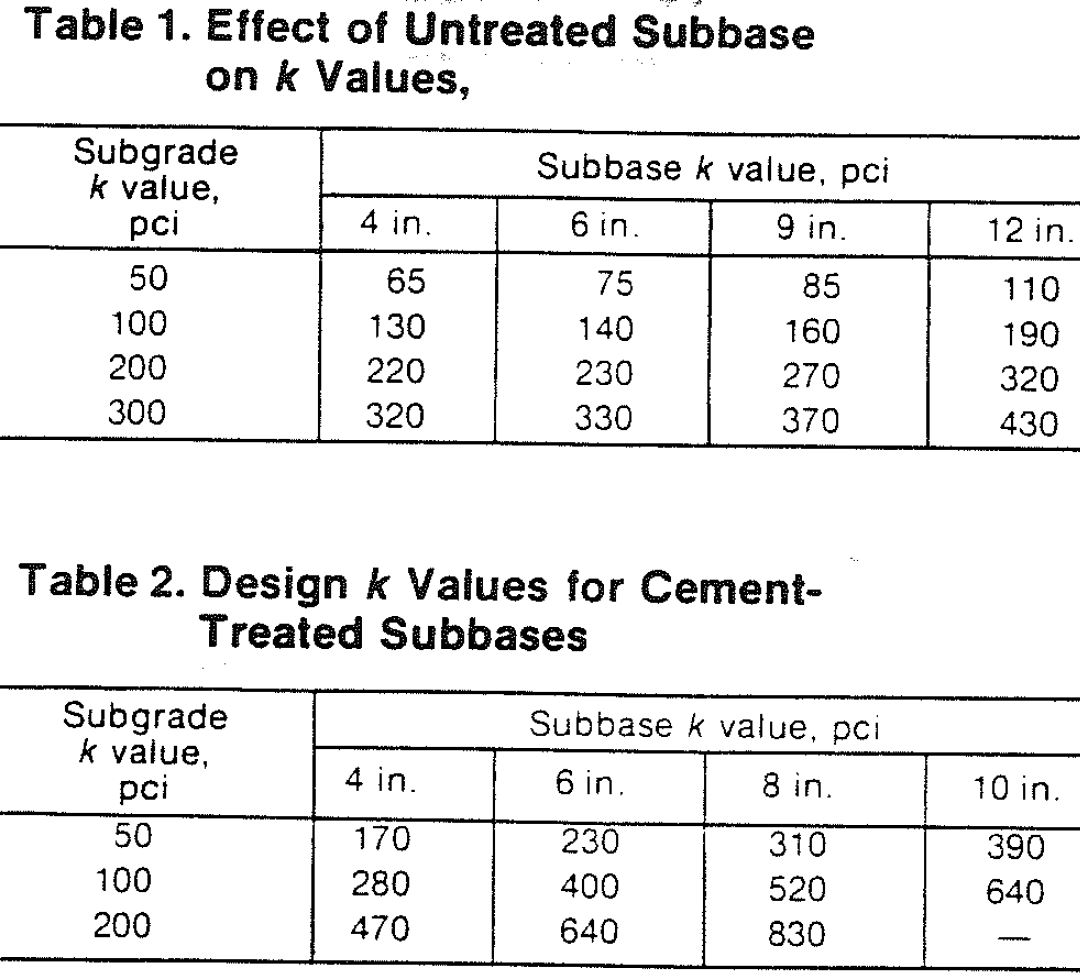
Use of a granular or hydraulically bound subbase beneath the slab will increase the effective subgrade reaction modulus. The PCA guide includes some guidance on the elevation of subgrade reaction modulus for different subbase types and thicknesses based on Burmister two layer model analysis. These tables are reproduced below (note the US units).
Load Safety Factors
The load safety factor in the PCA acts as a simple safety factor applied to the axle load. The PCA guide includes typical values of 1.2 for high volume roads, 1.1 for moderate use roads and 1.0 for less frequently used roads or for residential roads with predominantly light loadings.
Choosing the correct load safety factor includes considerations such as the consequences of failure and the likelihood of overloading. A major urban route with limited alternative routes may justify the use of a larger load safety factor to minimize the potential for repairs and maintenance during the design life of the road.
Joint Type
Jointed concrete roads can be installed with steel dowels which minimize differential movement between the two slabs either side of a joint. This has a big impact on the likelihood of pumping or other erosion type failures from occurring. The alternative is a joint with no steel which relies on aggregate interlock between the slabs to transfer the loads across the joint. This is much less effective than steel dowels in preventing erosion failures.
Where the PCA pavement design method analysis reveals that erosion type failure is the critical design case, the provision of steel dowels will significantly reduce the required thickness of slab. Steel dowels however do not have an effect on the fatigue resistance of the slab, therefore the provision of steel dowels will not affect the required thickness of pavements where fatigue is the critical design condition.
The inclusion of dowelled joints has the greatest effect on pavements without concrete shoulders. In many cases the most economical design is to include either dowelled joints or a concrete shoulder.
The PCA pavement design method models continuously reinforced concrete pavements in the same way as jointed concrete pavements with dowels.
Concrete Shoulders
The addition of concrete shoulders to the road has a significant beneficial effect to both the fatigue and erosion design conditions. The concrete shoulder prevents wheel loads from acting at the edge of the slab, effectively turning them into interior loads. Interior loads produce much smaller stresses in the pavement improving the fatigue performance. They also produce much smaller deflections and keep the wheel loads away from the slab corners which improves the erosion performance of the slab.
Including a concrete shoulder also allows the joints to be properly sealed without the seal being damaged by joint movements under loading. This minimizes the water able to enter the pavement through the slab joints which improves the durability of the pavement.
Including a concrete shoulder is however a significant additional cost. The additional cost can often be justified for heavily loaded concrete roads by reducing the required thickness of the slab.
Traffic Loads
The final input required is the precise traffic loading expected on the road during its design life. This is usually determined using existing traffic surveys and projections of traffic for new roads including growth factors for future use.
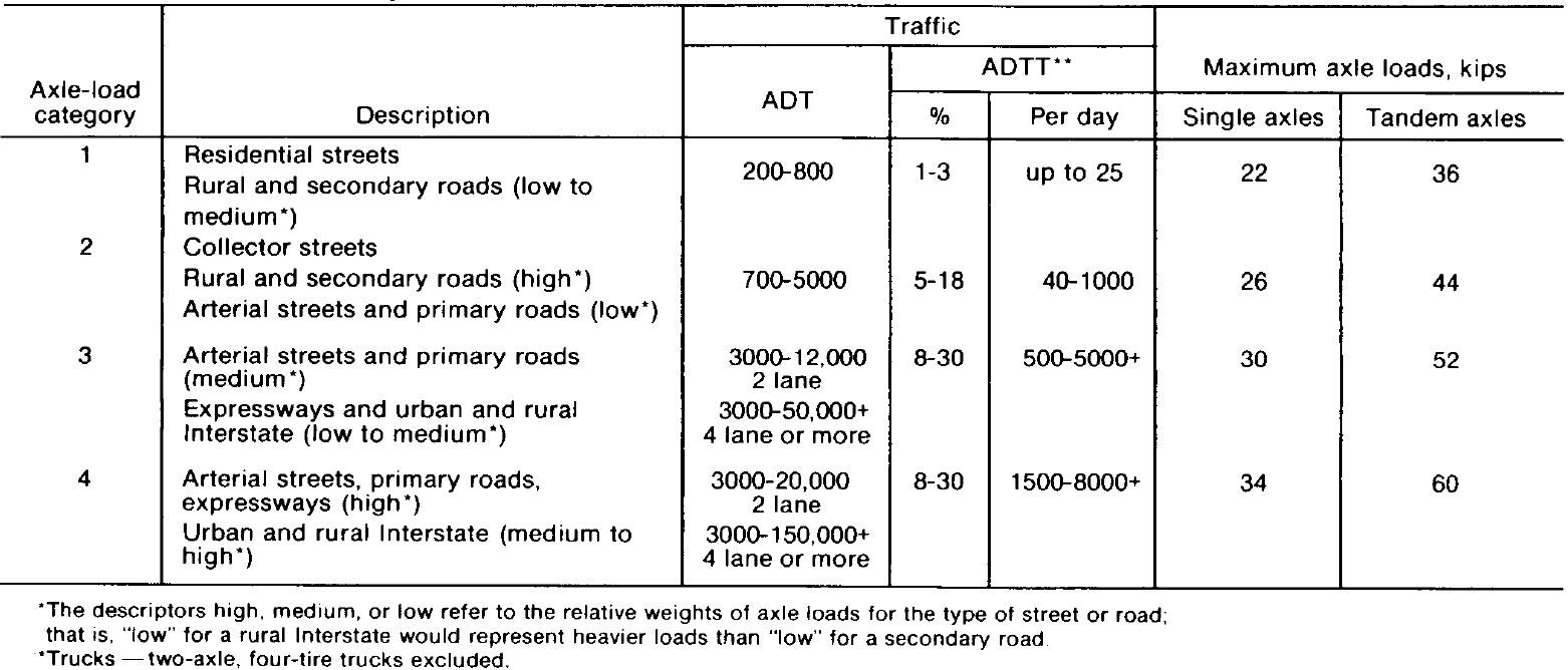
Where detailed traffic loading information is not available, the PCA guide includes a number of tables showing maximum allowable traffic loadings on concrete slabs of a particular thickness. Generic traffic loadings are split into 4 groups as in the table below.
For preliminary design the designer can choose a typical traffic loading group from the above table and then use the below tables to estimate a suitable design. The tables show an acceptable Average Daily Truck Traffic (ADTT) value for the pavement considered.
PCA Design for City Streets
The PCA further simplified the design procedure for urban roads in 1992 with the publication of “Design of Concrete Pavement for City Streets”. This publication assumed a typical urban traffic profile as detailed in the below table. This assumed profile was used to produce the following tables showing the maximum allowable ADTT for a number of typical road categories.
CivilWeb PCA Pavement Design Spreadsheet
Buy now for only £10.
Or why not buy our full Rigid Pavement Design suite for only £20
Or buy our best value bundle, the full Pavement Design Suite including flexible and rigid pavement spreadsheets for only £30
Download Free Trial Version
To try out a fully functional free trail version of this software, please enter your email address below to sign up to our newsletter.
