Concrete road design in the UK is undertaken in accordance with TRL 87. Jointed concrete pavement design for roads is in decline in the UK due to noise and performance issues, however it is still common to use TRL 87 to design repairs to concrete roads. TRL 87 is also used for the design of industrial and private concrete roads. Concrete Society Technical Report 66 still uses TRL 87 as its basis for concrete road design.
The CivilWeb TRL 87 Concrete Road Design Spreadsheet allows the designer to complete jointed concrete road and pavement designs in accordance with TRL 87 in seconds. Plus our unique design tools allow the designer to see at a glance exactly where the design can be optimised, saving time on iterative design approaches.
The CivilWeb TRL 87 Concrete Road Design Spreadsheet is available for purchase at the bottom of this page for just £10. Alternatively spreadsheet is included in the CivilWeb Rigid Pavement Design Spreadsheet Suite which includes 11 different pavement design methods along with a number of other useful design tools including concrete flexural strength calculators. Follow the above link for full details.
TRL 87 Concrete Road Design Method
The design of concrete roads in the UK is generally completed using the methodology recommended in the Transport and Road Research Laboratory Research Report 87 – Thickness Design of Concrete Roads (TRL 87). This report published in 1987 still forms the basis of concrete road design in the UK and has been reproduced in other design standards such as Highways Authority guidance HD 26/06 – Pavement Design and Concrete Society Technical Report 66 – External In-Situ Concrete Paving.
TRL 87 superseded Road Note 29 which was published in 1970. Road Note 29 included design curves based on limited performance data. TRL 87 was an attempt to improve the procedure for the design of concrete roads by including much more experimental data and then deriving empirical design equations. Equations were developed for two types of concrete roads, unreinforced and conventionally reinforced concrete roads.
Highways Agency guidelines HD 26/06 advise that rigid highways in the UK are only suitable with an asphalt surface. Unreinforced or reinforced jointed concrete roads are therefore not generally suitable for highways in the UK due to the difficulty in eradicating reflective cracking through the overlying asphalt surfacing. The design methods contained in TRL 87 are still suitable for private estate and industrial site roads and replacement, repair or widening works on existing jointed concrete pavement roads. Note continuously reinforced concrete pavements with asphalt surfacings are still suitable. These can be designed using the methods described in TRL Report 630 or using a design spreadsheet such as the CivilWeb Continuously Reinforced Concrete Pavement Design Spreadsheet.
TRL 87 - Equivalent Foundation Modulus
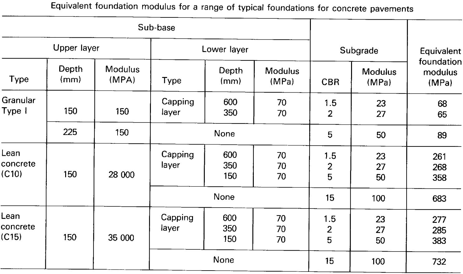
The TRL 87 method assumes that the support from the road foundations can be simplified to an equivalent foundation modulus describing the Young’s modulus of an infinitely deep elastic support layer. TRL 87 included a table giving typical equivalent foundation modulus values for a range of common road foundations, presented below.
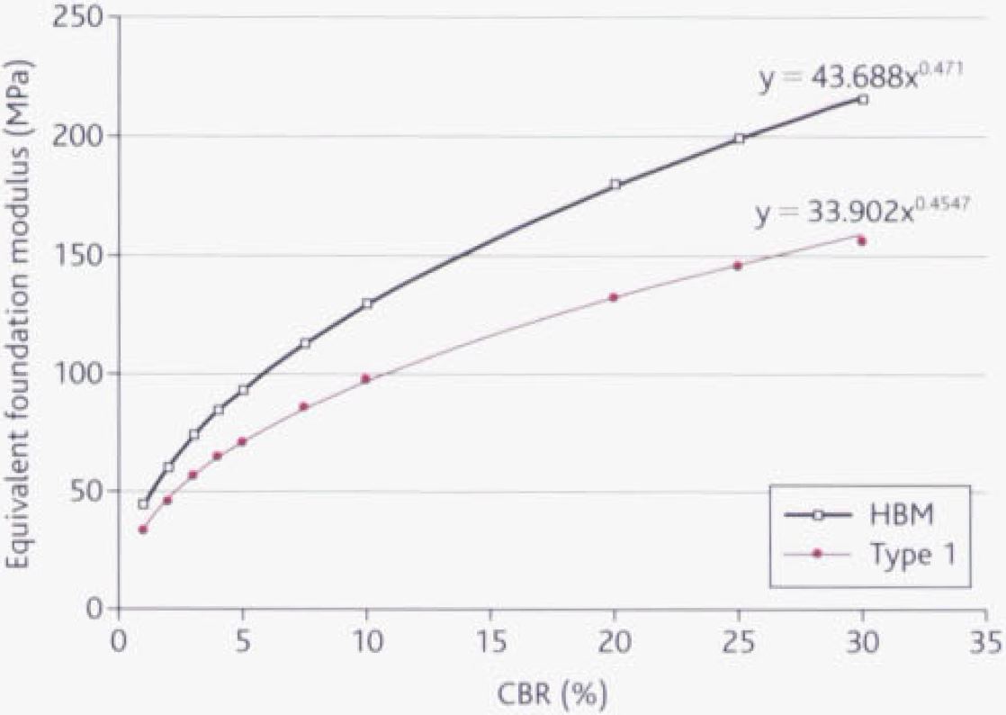
Concrete Society publication TR66 expanded on these recommendations to derive equivalent foundation modulus values dependent on subgrade CBR values for two common foundation types, 150mm of Type 1 sub-base and 150mm of Hydraulically Bound Material (HBM) sub-base. In most cases these values are sufficient for concrete road design. The CivilWeb TRL 87 Concrete Road Design Spreadsheet calculates an equivalent foundation modulus value using the below equations, as shown in the below graph. The spreadsheet also allows the user to override these values with their own where better information or a different type of foundation is proposed.
TRL 87 Unreinforced Concrete Road Design
Unreinforced concrete roads are individual concrete slabs separated from others by undowelled contraction joints. The empirical design equation derived in TRL 87 for unreinforced concrete roads is shown below where L is the lifetime traffic loading, h is the slab thickness, fcm,cube is the 28 day mean compressive cube strength, M is the foundation equivalent modulus and F is the percentage of failed bays which constitutes the failure condition. Note that these equations assume that the wheels are able to approach the concrete edge, ie no concrete shoulder is present.
In the Concrete Society publication TR 66 this equation is rearranged to give the required pavement thickness directly, as shown below.
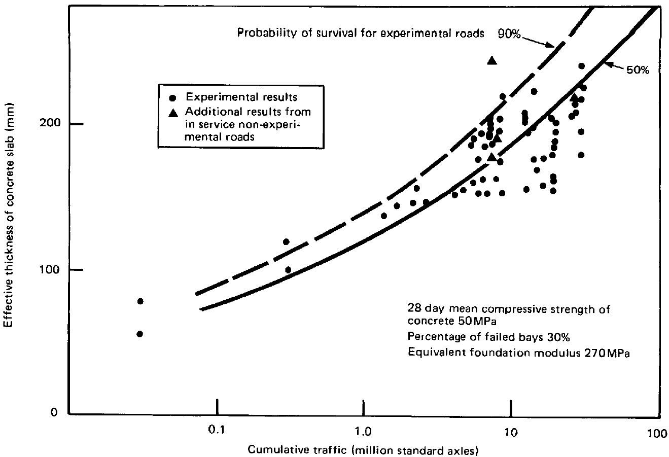
TRL 87 also included a simplified relationship based on only the slab thickness and the traffic loading which are closely related. For typical values of the other parameters (concrete strength of 50MPa, foundation modulus of 270MPa and 30% bay failure) the following equation was derived.
This relationship was overlaid over the experimental results and some non-experimental road data and 90% and 50% confidence limits were shown. This was illustrated in a graph which has been reproduced below.
TRL Conventionally Reinforced Concrete Road Design
Conventionally reinforced concrete roads include reinforcing fabric at the bottom of the slab. Generally there should be more than 300mm2 of reinforcement per m of slab for the slab to qualify as reinforced. If less than 300mm2 is included the slab should be designed as unreinforced.
The empirical design equation derived in TRL 87 is shown below where As is the area of reinforcement per m width of slab. Again this equation assumes that there is no concrete shoulder and wheel loads can approach the edge of the slab.
Again the Concrete Society publication TR66 includes a rearraged version of this equation to give the required slab thickness directly, as shown below.
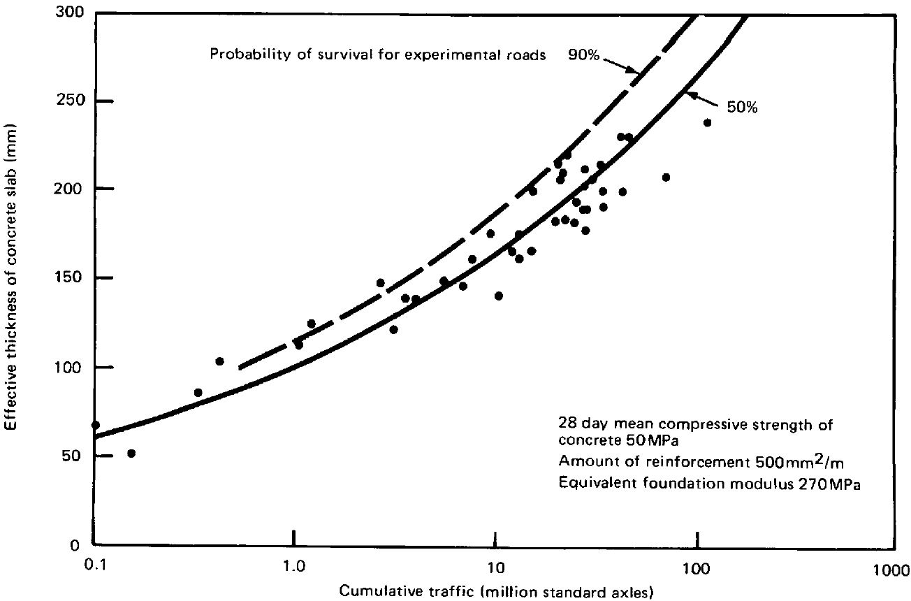
Similar to the unreinforced concrete slabs, a simplified relationship between slab thickness and traffic load was derived. The equation below assumes values of concrete strength of 50MPa, reinforcement area of 500mm2 and a foundation modulus of 270MPa.
Again this equation with confidence limits was overlaid over the experimental data in the graph shown below;
Concrete Shoulders
The addition of concrete shoulders of at least 1.0m width tied to the main slab has a significant effect on the stresses produced in the slab. The concrete shoulders effectively turn edge loadings into interior loadings.
TRL 87 did not consider this effect directly as no experimental data from the UK was available at the time. However a comparison with the AASHTO design guide published in 1985 was made and the two methods were found to be largely equivalent. In this case it was deemed reasonable for the TRL 87 guide to include the AASHTO concrete shoulder relationship within its guidelines. The below equation is used to convert the design thicknesses derived from TRL 87 to pavements including a concrete shoulder where H1 is the thickness without a concrete shoulder and H2 is the thickness with a concrete shoulder.
CivilWeb TRL 87 Concrete Road Design Spreadsheet
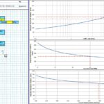
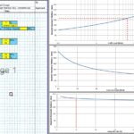
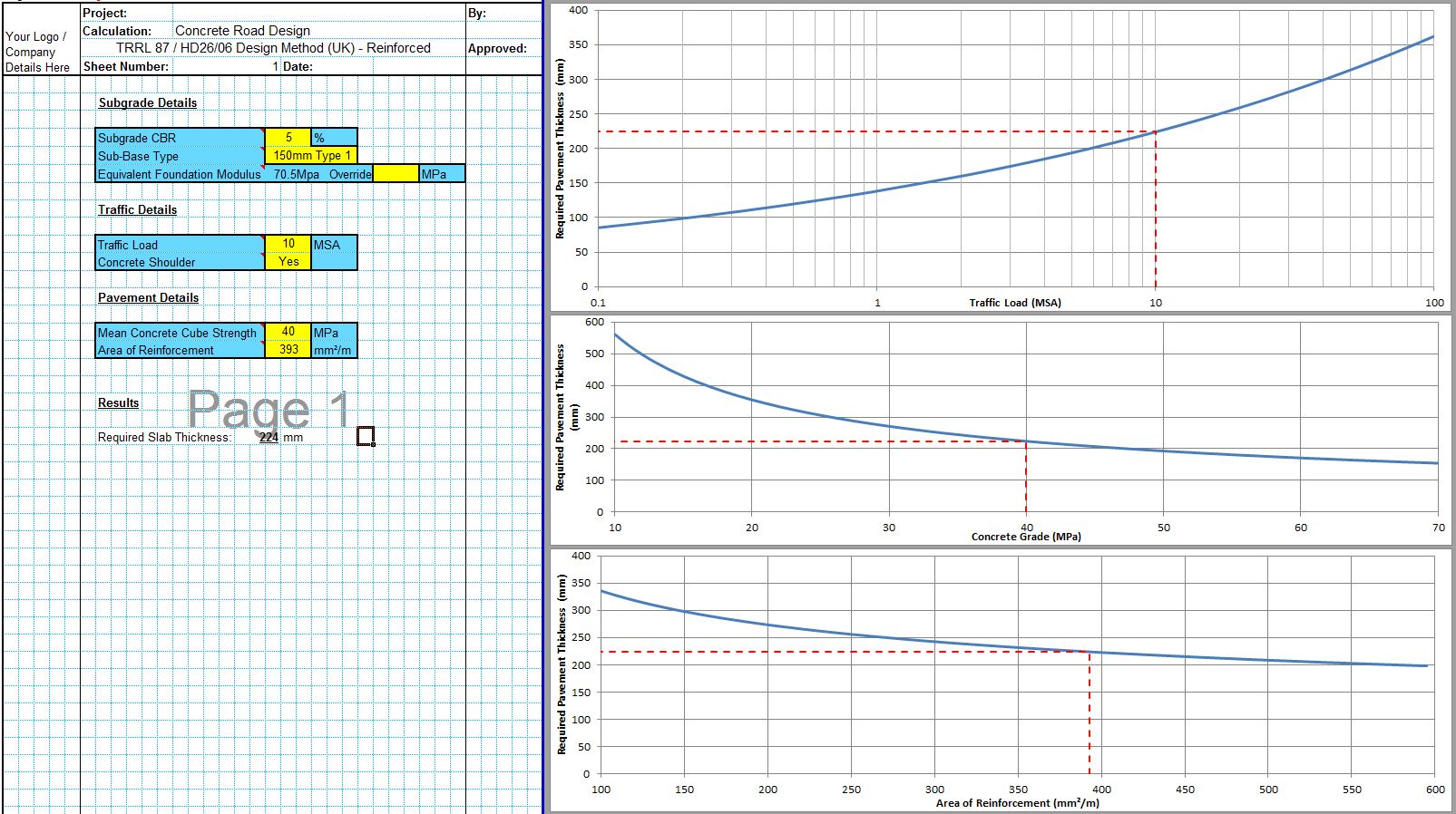
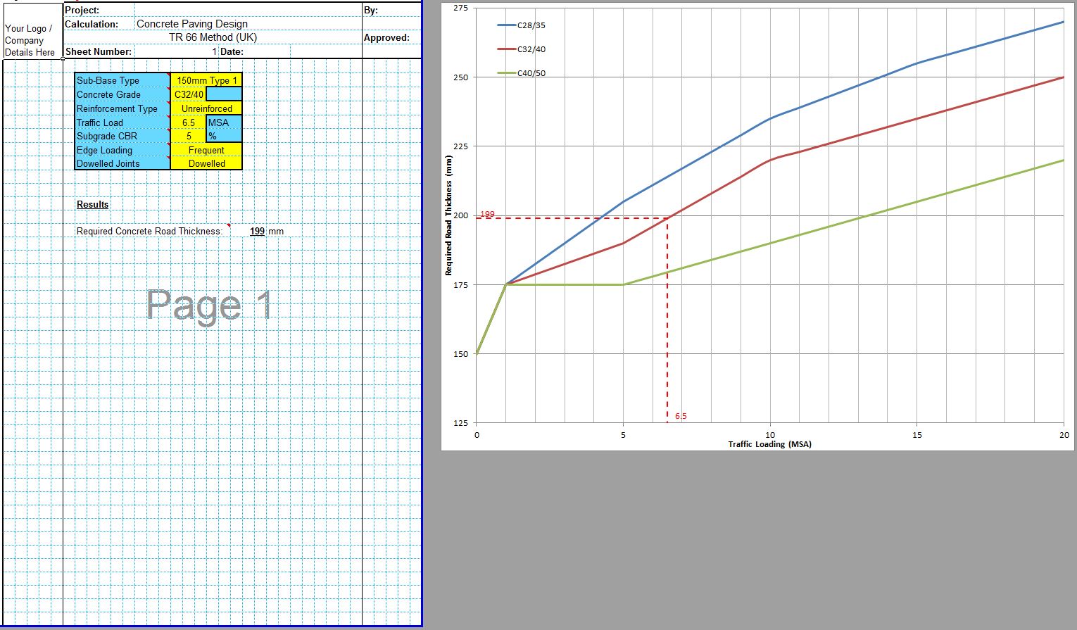
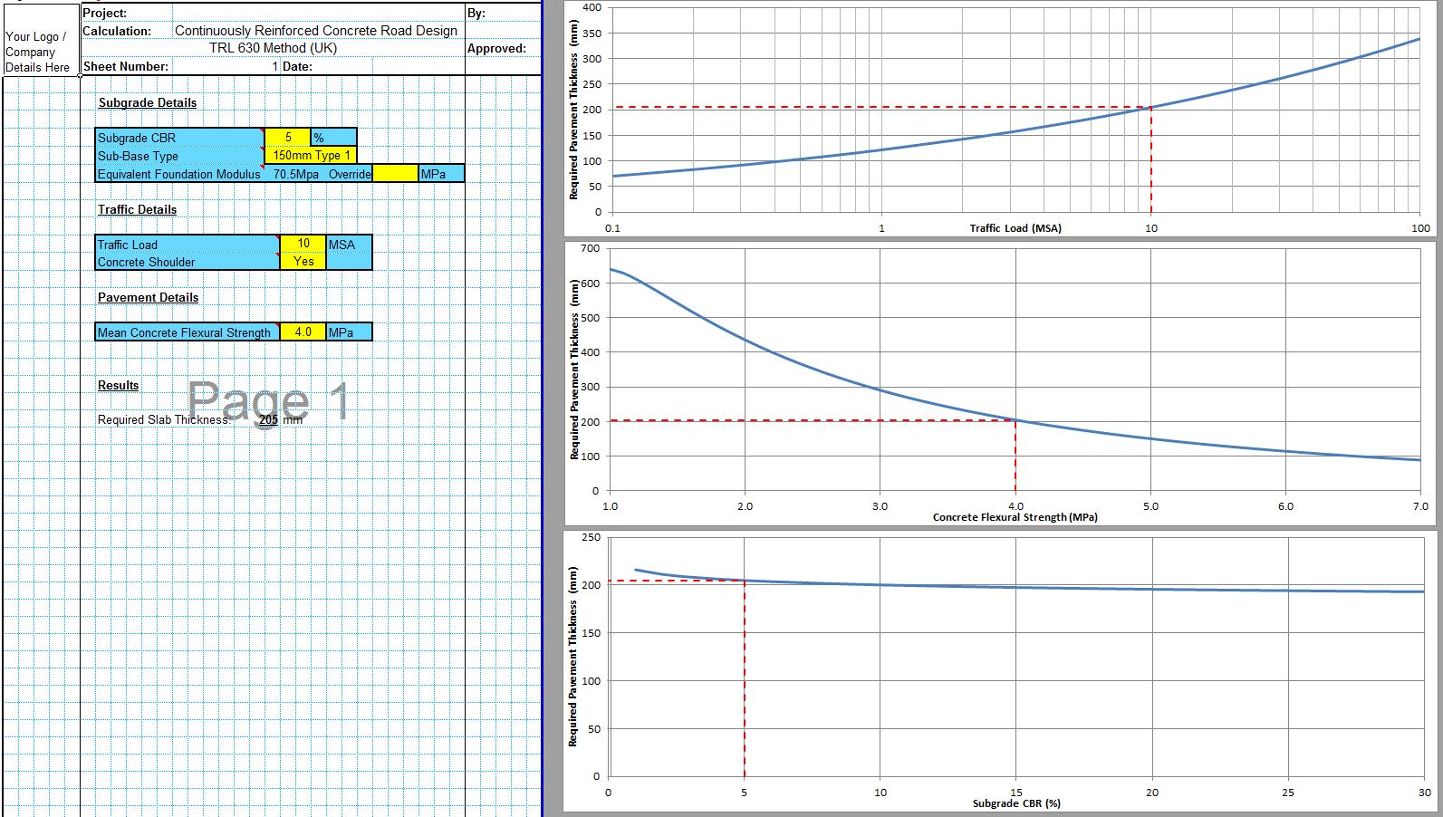
The CivilWeb TRL 87 Concrete Road Design Spreadsheet completes the thickness design for the proposed pavement instantly using only a handful of inputs. This allows the designer to complete a fully TRL 87 compliant design in seconds.
The spreadsheet also includes unique design tools showing the thickness results for alternative traffic loads, concrete strengths and subgrade strengths. This allows the designer to see at a glance whether the design can be optimised.
Buy now for only £10
Or why not buy our full Rigid Pavement Design suite for only £20
Or buy our best value bundle, the full Pavement Design Suite including flexible and rigid pavement spreadsheets for only £30
Download Free Trial Version
To try out a fully functional free trail version of this software, please enter your email address below to sign up to our newsletter.
